Aneurysm stent with growth factor

a growth factor and aneurysm technology, applied in the field of surgical repair of aneurysms, can solve the problems of affecting the blood flow in the remaining vessel, and affecting the healing effect of the aneurysm

Active Publication Date: 2007-07-10
THRAMANN JEFREY
View PDF19 Cites 61 Cited by
  • Summary
  • Abstract
  • Description
  • Claims
  • Application Information

AI Technical Summary

Benefits of technology

[0012]The foregoing and other features, utilities and advantages of the invention will be apparent from the following more particular description of a preferred embodiment of the invention as illustrated in the accompanying drawings.

Problems solved by technology

Recent studies have found, however, that the body breaks down conventional treatments re-exposing blood flow to the aneurysm.
One drawback of endovascular treatment of the aneurysm includes the potential to over pack the aneurysm.
Over packing the aneurysm can cause the material to enter the parent blood vessel, potentially altering blood flow in the remaining vessel or generating undesirable pressure in the aneurysm.
Wide neck aneurysms have the additional risk that the occluded material will break free of the aneurysm and enter the parent blood vessel, potentially causing blockage of the parent blood vessel.
Finally, clotting agents and polymers used to form occlusions in the aneurysm can seep to the parent blood vessel causing complications.
Balloons and liners are intuitively pleasing as a solution, but have the potential for an inexact fit causing complications.
For example, a balloon may be over inflated causing unwanted pressure or under inflated causing seepage in the aneurysm.
While the Boock device 30 seemingly works for its intended purpose in theory, its relatively large size and surface area makes its impractical to actually use.

Method used


Image

  • Aneurysm stent with growth factor
  • Aneurysm stent with growth factor
  • Aneurysm stent with growth factor

Examples


Embodiment Construction

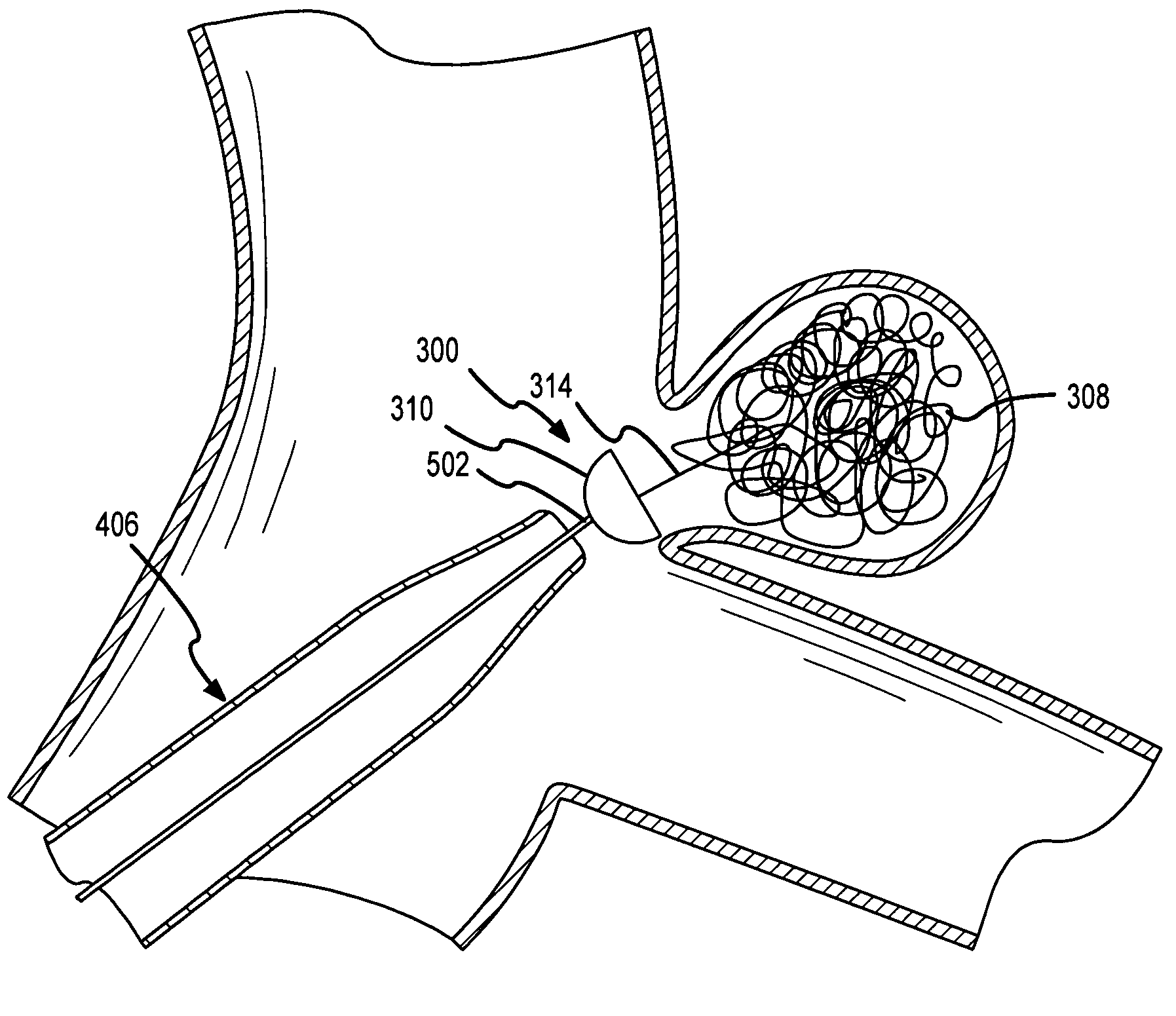
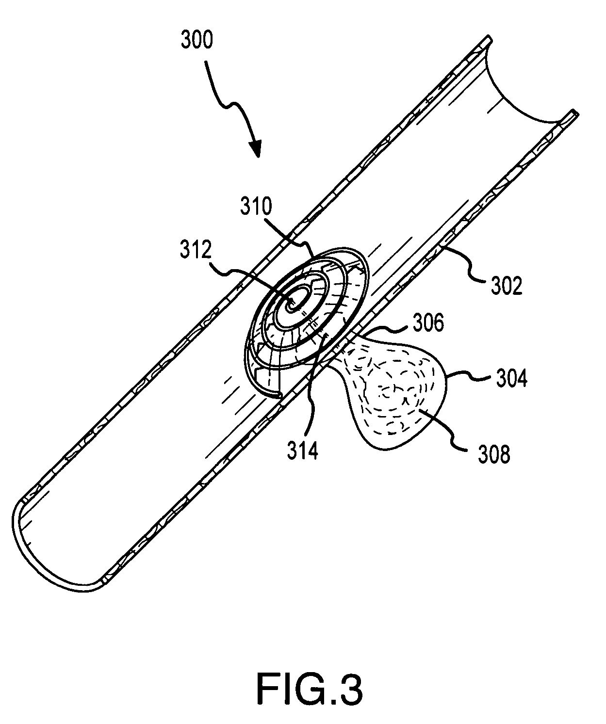
[0024]Some embodiments of the present invention are described with reference to FIGS. 3 to 10B. FIG. 3 shows an aneurysm stent 300 consistent with an embodiment of the present invention deployed. Stent 300 is deployed in a parent blood vessel 302, which is shown as an artery but could be a vein a capillary, or the like, about aneurysm 304. A blood flow path from vessel 302 to aneurysm 304 is provided by an aneurysm neck 306. Neck 306 is shown as a narrow neck, but could be a wide neck. Aneurysm 304 is shown packed with conventional GDCs 308. While shown as packed with conventional coils, aneurysm 304 could be packed with any type of packing agent, such as, for example, other types of coils, balloons, glues, polymers, clotting agents, liners, or the like. In fact, aneurysm 304 does not need to be packed at all as stent 300 blocks blood flow to aneurysm 304. The attachment of stent 300 to cover neck 306 will depend, in part, on the type of material used to pack aneurysm 304, if any. W...


PUM


Abstract

The present invention relates to an aneurysm stent having a base and connector. The base has a vessel facing side and an aneurysm facing side, and is shaped to cover an aneurysm sufficiently. The connector is coupled to the aneurysm facing side of the base such that when deployed the connector is adapted to extend partially into the aneurysm to anchor the base about the aneurysm and alter flow into the aneurysm. Further, the stent can be used as a delivery mechanism to deliver growth factor.

Description

[0001]The present application is a continuation-in-part of U.S. patent application Ser. No. 10 / 455,145, filed Jun. 4, 2003, titled: Aneurysm Stent, which claims the benefit of U.S. Provisional Patent Application Ser. No. 60 / 404,422, filed Aug. 19, 2002, titled A Cerebral Aneurysm Coil Sent, both of which are incorporated herein by reference.FIELD OF THE INVENTION[0002]The present invention relates to the surgical repair of aneurysms and, more particularly, to a patch that provides a seal between the arterial wall and a neck of the aneurysm to alter flow in the aneurysm.BACKGROUND OF THE INVENTION[0003]An aneurysm is a blood-filled dilation of a blood vessel. Major concerns with aneurysms revolve around rupturing of the arterial wall causing internal bleeding and clots breaking away from the aneurysm causing strokes.[0004]There exist two generally approved methods of treating aneurysms. The first method of treatment includes surgical treatment. The second method of treatment includes...

Claims


Application Information

Patent Timeline
Patent Type & Authority Patents(United States)
IPC IPC(8): A61B17/08A61B17/00A61B17/12A61FA61F2/82
CPCA61B17/12022A61B17/12136A61B17/12172A61F2/91A61F2/915A61F2/95A61B17/12113A61F2230/0095A61B2017/00867A61B2017/1205A61B2017/12068A61F2/852A61F2/958A61F2002/30329A61F2002/30545A61F2002/30599A61F2002/826A61F2002/828A61F2002/91508A61F2002/91525A61F2002/91533A61F2002/91541A61F2002/91558A61F2002/91575A61F2002/91591A61F2002/9665A61F2220/0025A61F2250/001A61F2250/0063A61F2250/0071
Inventor THRAMANN, JEFFREY J.FULTON, MICHAEL
Owner THRAMANN JEFREY
Why Eureka
Try Eureka