Oil filter canister removal tool

a technology for oil filter canisters and removal tools, which is applied in the direction of liquid handling, separation processes, applications, etc., can solve the problems of difficult cleaning operations, and achieve the effects of convenient rotation, simple and inexpensive removal tools, and preventing the dripping of dirty oil

Inactive Publication Date: 2007-07-10
CLINE DANIEL B
View PDF7 Cites 22 Cited by
  • Summary
  • Abstract
  • Description
  • Claims
  • Application Information

AI Technical Summary

Benefits of technology

[0003]My invention is a simple inexpensive removal tool for oil filter canisters which is effective in preventing the dripping of dirty oil from the filter canister during the removal process. In general my invention comprises a cup-shaped tool which fits over the oil filter canister, is of sufficient length to fully receive and enclose the oil filter canister, and is of sufficient diameter to create a clearance between the oil filter canister and the open top rim of the tool so that oil dripping from the oil filter canister during the removing operation falls into the tool rather than onto the floor or into the bilge of a boat. I provide a snug fit between my tool and the oil filter canister so that rotation of the tool rotates the oil filter canister to complete the removal operation once it has been loosened using a conventional oil filter wrench. The snug fit can be provided in a number of ways including (a) molding integral inwardly projecting ribs or flutes into the body of the cup-shaped tool, or (b) placing strips of elastomeric material in circumferentially spaced relationship along the inner surface of the tool body. Using these or other similar techniques the radial clearance between the tool body and the filter canister is maintained for the purpose of catching oil while, at the same time, a snug fit between the body and the oil filter canister is provided so that the oil filter canister is easily rotated for removal purposes.

Problems solved by technology

The dirty oil typically drips onto a garage floor or, in the case of a marine engine, into the bilge of the boat where space constraints make clean up operations particularly difficult.

Method used


Image

  • Oil filter canister removal tool
  • Oil filter canister removal tool
  • Oil filter canister removal tool

Examples


Embodiment Construction

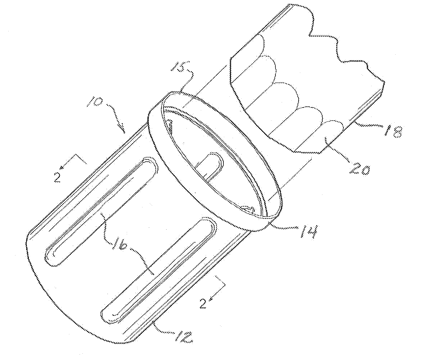
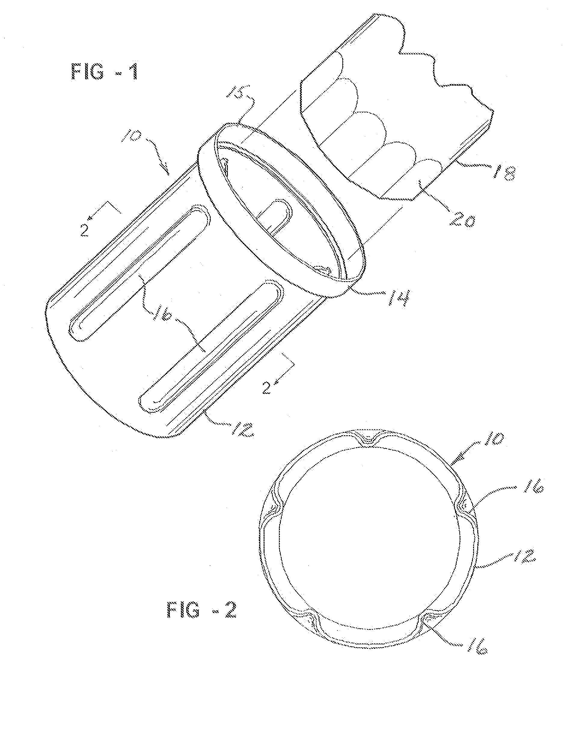
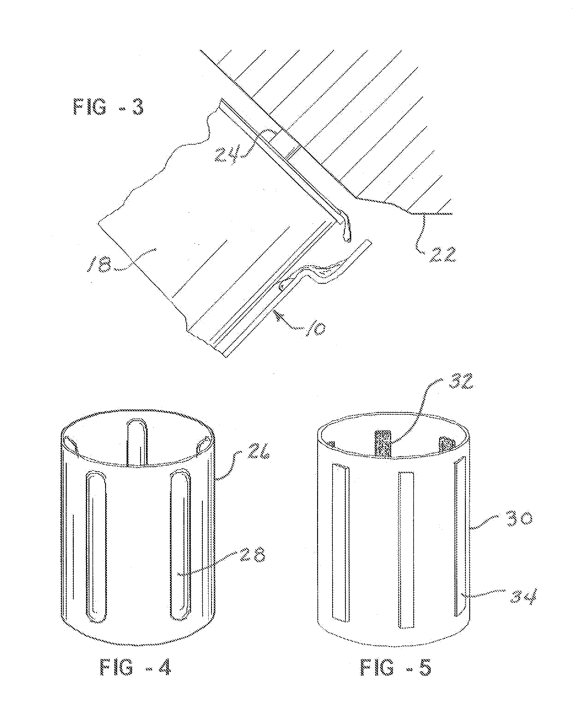
[0009]Referring now to FIGS. 1–3, a drip-catching removal tool 10 for an oil filter canister 18 is shown to comprise a cup-shaped body 12 having an enlarged diameter band portion 14 near the top rim 15 as well as a plurality of longitudinally extending, circumferentially spaced, inwardly projecting ribs or flutes 16 formed therein. The body 12, in combination with the rim band 14, is of sufficient length so as to fully receive and enclose the body of a conventional oil filter canister 18. The diameter of the body 12, except for the inwardly projecting flutes 16, is of sufficient diameter so as to create a radial clearance or gap between the filter canister 18 and the inner surface of the body 12. The band 14 is stepped out from the body 12 approximately ⅛ to 3 / 16 of an inch to create additional clearance for the catching of oil drips as best shown in FIG. 3. The flutes or ribs 16 project inwardly by a sufficient amount to fit snugly against the body of the oil filter canister 18 so ...


PUM

PropertyMeasurementUnit
diameteraaaaaaaaaa
lengthaaaaaaaaaa
relative sizeaaaaaaaaaa

Abstract

An oil filter canister removal tool comprising a cup-shaped plastic body long enough to receive the filter therein and of sufficient diameter as to provide radial clearance between the filter canister and the top rim of the body. A snug fit can be provided by integral flutes or bonded in strips of elastomeric material. In operation the tool is slipped over a canister after the canister has been loosened relative to the engine block. The tool is manually rotated until the canister is free of the engine. The tool can be cleaned up and reused after disposal of the oil filter canister. The tool may also be thrown away with the used filter.

Description

FIELD OF THE INVENTION[0001]My invention relates to oil filter canister removal tools and more particularly to a cup-shaped tool which is effective to prevent the dripping of oil during a filter canister removal operation.BACKGROUND OF THE INVENTION[0002]I have found that it is common for a small quantity of dirty oil to drip from an oil filter canister during the process of removing the used oil filter canister from the threaded connection with an engine block. The dirty oil typically drips onto a garage floor or, in the case of a marine engine, into the bilge of the boat where space constraints make clean up operations particularly difficult.SUMMARY OF THE INVENTION[0003]My invention is a simple inexpensive removal tool for oil filter canisters which is effective in preventing the dripping of dirty oil from the filter canister during the removal process. In general my invention comprises a cup-shaped tool which fits over the oil filter canister, is of sufficient length to fully re...

Claims


Application Information

Patent Timeline
Patent Type & Authority Patents(United States)
IPC IPC(8): B01D27/08B25B13/06
CPCB01D35/30B25B27/0042B01D2201/24
Inventor CLINE, DANIEL B.
Owner CLINE DANIEL B
Why Eureka
Try Eureka