Combined test instrument probe and voltage detector

a technology of voltage detector and test instrument, which is applied in the field of combined test instrument probe and voltage detector, can solve the problems of easy loss of devices, non-reading situation, and danger for users relying on instruments

Active Publication Date: 2007-07-10
JOHN FLUKE MFG CO INC
View PDF21 Cites 36 Cited by
  • Summary
  • Abstract
  • Description
  • Claims
  • Application Information

AI Technical Summary

Problems solved by technology

A problem exists in situations where an instrument user connects a probe to a potentially dangerous a.c. voltage source and gets no reading when in fact a high voltage is present.
This non-reading situation may arise from broken or disconnected test leads, broken a.c. receptacles, or even when the test instrument is in a different measuring mode from that intended.
Incorrect readings or an indication that no voltage is present when in fact a dangerous voltage exists may create a dangerous situation for the user relying on the instrument.
While quite useful, these devices are easily lost because of their small size, or are simply forgotten when a technician takes a test instrument to measure an electrical circuit.

Method used


Image

  • Combined test instrument probe and voltage detector
  • Combined test instrument probe and voltage detector
  • Combined test instrument probe and voltage detector

Examples


Embodiment Construction

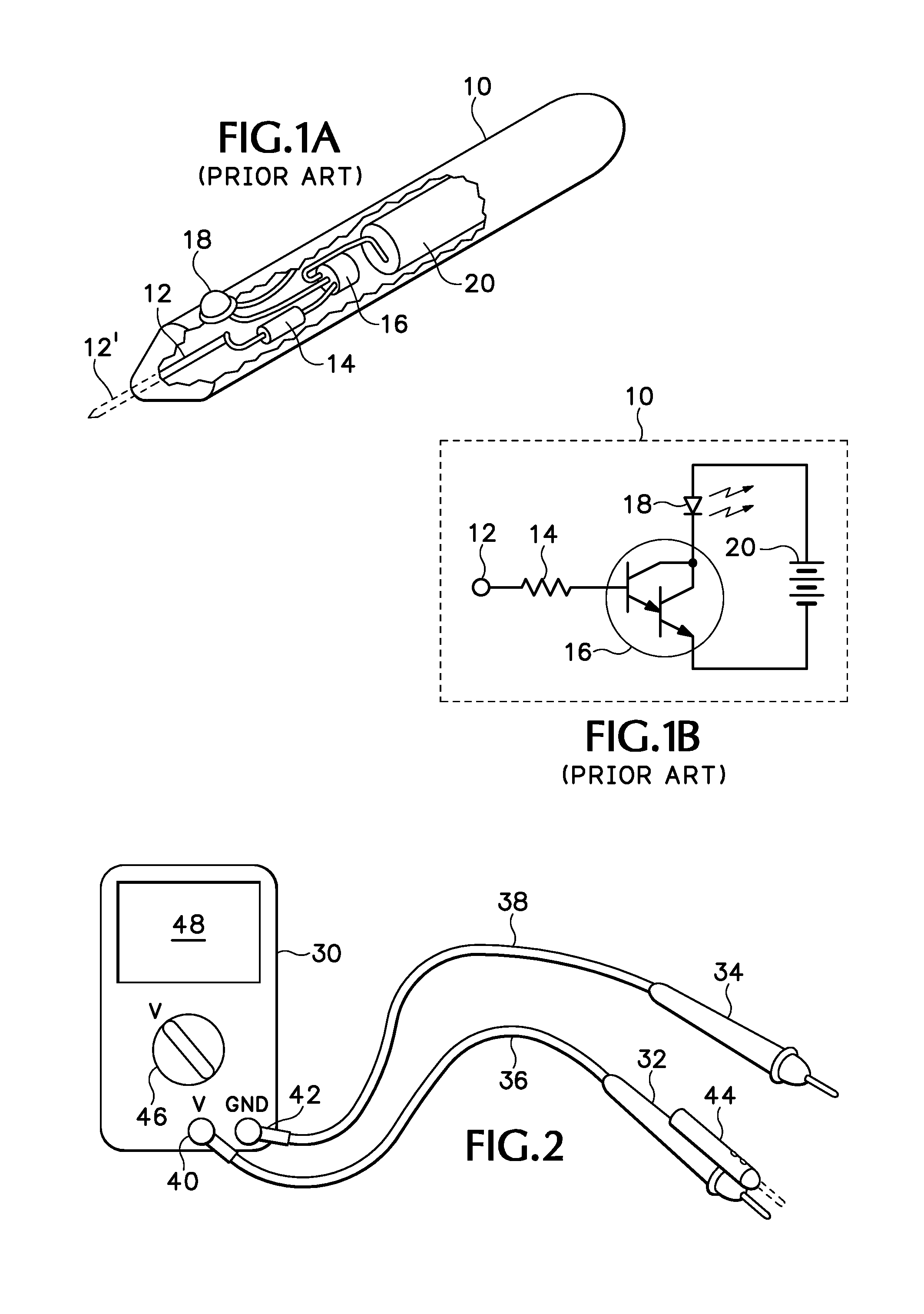
[0014]Referring to FIG. 1A of the drawings, there is shown a cut-away view of a prior art voltage detector 10, showing the internal components. FIG. 1B is a schematic of the electrical circuit within the voltage detector 10. The following description applies to both FIGS. 1A and 1B. In the case of a noncontacting voltage detector, a sensor element 12 is completely insulated from the external portion of the voltage detector, and senses a.c. electrical fields through capacitive coupling. In the case of a contacting voltage detector, element 12′ extends through one end of the voltage detector to form an electrically conductive contacting tip as shown in phantom. The element 12-12′ is connected via a resistor 14 to the base of a transistor 16, which is shown as a high-gain Darlington transistor. The collector transistor 16 is connected through a light-emitting diode (LED) 18 to the positive terminal of a battery 20. The emitter of transistor 16 is connected to the negative terminal of b...


PUM


Abstract

A voltage detector is combined with a test instrument probe to provide an indication of the presence of a.c. voltage when the test instrument probe approaches or comes in contact with a source of a.c. voltage.

Description

BACKGROUND OF THE INVENTION[0001]This invention relates generally to test instrument probes, and in particular to a combined test instrument probe and voltage detector.[0002]Test instruments such as digital multimeters, analog volt-ohmmeters, oscilloscopes and the like are used to measure electrical parameters such as a.c. and d.c. voltages and currents. Test probes are used to connect test instruments to electrical or electronic circuits so that measurements may be made. A problem exists in situations where an instrument user connects a probe to a potentially dangerous a.c. voltage source and gets no reading when in fact a high voltage is present. This non-reading situation may arise from broken or disconnected test leads, broken a.c. receptacles, or even when the test instrument is in a different measuring mode from that intended. Incorrect readings or an indication that no voltage is present when in fact a dangerous voltage exists may create a dangerous situation for the user rel...

Claims


Application Information

Patent Timeline
Patent Type & Authority Patents(United States)
IPC IPC(8): G01R19/155G01R1/06G01R1/067
CPCG01R1/04G01R1/067
Inventor CAVORETTO, JAMES L.
Owner JOHN FLUKE MFG CO INC
Why Eureka
Try Eureka