Method and apparatus for automatic registration and visualization of occluded targets using ladar data

a technology applied in the field of automatic registration and visualization of occluded targets using ladar data, can solve the problems of difficult segmentation of 2d image into object and occluder pixels, insufficient light from the object, and impracticality of achieving this goal with a 2d sensor, so as to enhance the visual exploitation of aligned and aggregated ladar frames

Active Publication Date: 2007-07-10
SRI INTERNATIONAL
View PDF11 Cites 51 Cited by
  • Summary
  • Abstract
  • Description
  • Claims
  • Application Information

AI Technical Summary

Problems solved by technology

But achieving this goal with a 2D sensor is impractical for three reasons: the pores may be smaller than the sensor's pixel resolution, insufficient light from the object may reach the sensor, and segmenting a 2D image into object and occluder pixels is difficult.
However, weight, cost, and real-time constraints may preclude such accurate pose measurement in certain applications.

Method used


Image

  • Method and apparatus for automatic registration and visualization of occluded targets using ladar data
  • Method and apparatus for automatic registration and visualization of occluded targets using ladar data
  • Method and apparatus for automatic registration and visualization of occluded targets using ladar data

Examples


Embodiment Construction

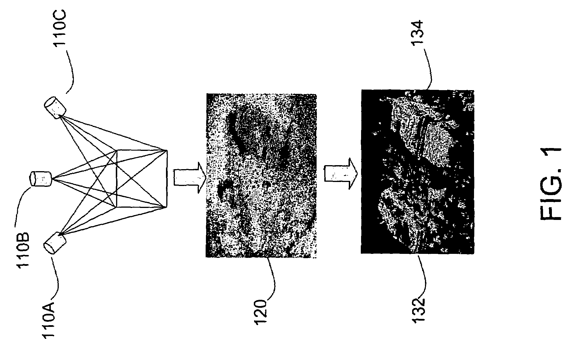
[0023]Embodiments of the present invention show some characteristics of ladar frames collected by sensors in an operational scenario. FIG. 1 illustrates a set of sensors 110A-C adapted to collect data from a scene. Although there are only three sensors shown in FIG. 1, more could be utilized to implement the present invention. Alternatively, 110A-C in fact may illustrate only a single ladar sensor that is moved to three different locations. Sensors 110A-C may be ladar sensors or some other visual data collection device. Sensors 110A-C may be carried by a person or deployed on any land, airborne, or amphibious vehicle, e.g., a motor vehicle, airplane, helicopter, boat, or a remotely controlled vehicle. Targets of interest 132, 134 are viewed through a dense scattering medium, e.g. a mass of foliage 120. Since the foliage 120 blocks almost all the rays to the targets 132, 134, the 3D points on the target surface may be sparse and irregular—too few for data-driven registration. Therefo...


PUM


Abstract

A method and apparatus for high-resolution 3D imaging ladar system which can penetrate foliage and camouflage to sample fragments of concealed surfaces of interest is disclosed. Samples collected while the ladar moves can be integrated into a coherent object shape. In one embodiment, a system and method for automatic data-driven registration of ladar frames, comprises a coarse search stage, a pairwise fine registration stage using an iterated closest points algorithm, and a multi-view registration strategy. After alignment and aggregation, it is often difficult for human observers to find, assess and recognize objects from a point cloud display. Basic display manipulations, surface fitting techniques, and clutter suppression to enhance visual exploitation of 3D imaging ladar data may be utilized.

Description

CROSS-REFERENCE TO RELATED APPLICATIONS[0001]This application claims benefit of U.S. provisional patent application Ser. No. 60 / 463,761, filed Apr. 18, 2003, and 60 / 464,555, filed Apr. 22, 2003 which are herein incorporated by reference.GOVERNMENT RIGHTS IN THIS INVENTION[0002]This invention was made with U.S. government support under contract number DAAD17-01-D-004, DAAD17-01-C-0055, F33615-02-C1265 and DAAD17-01-D-0006. The U.S. government has certain rights in this invention.BACKGROUND OF THE INVENTION[0003]The present invention generally relates to the ability to detect and recognize objects hidden behind porous occluders, such as foliage and camouflage, thereby enhancing operations in public safety, law enforcement, and defense. While any instantaneous view of the scene might contain rays hitting only a fraction of the object surface of interest, different fragments could be exposed by moving the object, the occluder, or the sensor. Theoretically, the aggregation of a diverse s...

Claims


Application Information

Patent Timeline
Patent Type & Authority Patents(United States)
IPC IPC(8): G01C3/08G01B9/02G01B11/14G01J3/45G06T
CPCG06K9/3241G06T7/0024G06T7/0028G06T5/002G06T5/20G01S17/89G06T2200/04G06T2207/10028G06T2207/20016G06T2207/30212G06T2207/30236G06T7/30G06T7/33G06V10/255
Inventor HSU, STEPHEN CHARLESSAMARASEKERA, SUPUNKUMAR, RAKESHZHAO, WEN-YIHANNA, KEITH J.
Owner SRI INTERNATIONAL
Why Eureka
Try Eureka