Optical pulse calibration for quantum key distribution

a quantum key and optical pulse technology, applied in the field of quantum cryptography, can solve the problems of inability to realize the information about the key obtained by an eavesdropper, inability to perform the needed attenuation, and inability to realize the effect of attenuation,

Inactive Publication Date: 2007-07-10
MAGIQ TECH INC
View PDF16 Cites 32 Cited by
  • Summary
  • Abstract
  • Description
  • Claims
  • Application Information

AI Technical Summary

Problems solved by technology

As a consequence, an eavesdropper (“Eve”) that attempts to intercept or otherwise measure the quantum signal will introduce errors into the transmitted signals, thereby revealing her presence.
Because only the key is transmitted in a QKD system, any information about the key obtained by an eavesdropper is useless if no message based on the key is sent between Alice and Bob.
While people generally understand that optical pulses need to be attenuated in QKD, the practical aspects of performing the needed attenuation tend to remain unappreciated and overlooked.
If the pulses are too strong, they will no longer be at the single-photon level and the security of the QKD is compromised.
On the other hand, if the pulses are too weak, then, many pulses will go undetected, which reduces the key transmission rate.
A commercially viable QKD system will have sources of loss that arise from a number of internal and external factors, such as quantum channel inherent loss, environmental effects, fiber splices, fiber type and length, etc., that are different for each installation.
This makes the process of providing pulses with a well-defined, small intensity quite daunting—to the point where the prior art methods for attenuating optical signals used in other optical technologies are not applicable to a high-performance, commercially viable QKD system.
The use of stronger optical pulses for self-calibration and set-up of a QKD system is currently neglected in the prior art.

Method used


Image

  • Optical pulse calibration for quantum key distribution
  • Optical pulse calibration for quantum key distribution
  • Optical pulse calibration for quantum key distribution

Examples


Embodiment Construction

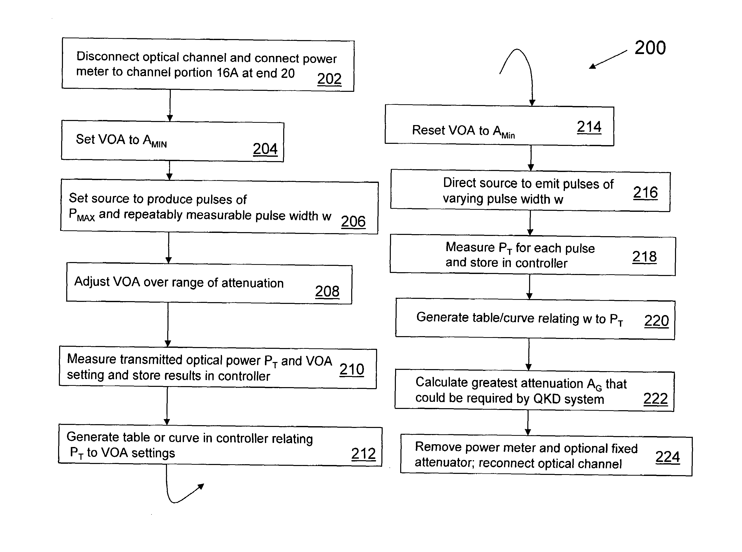
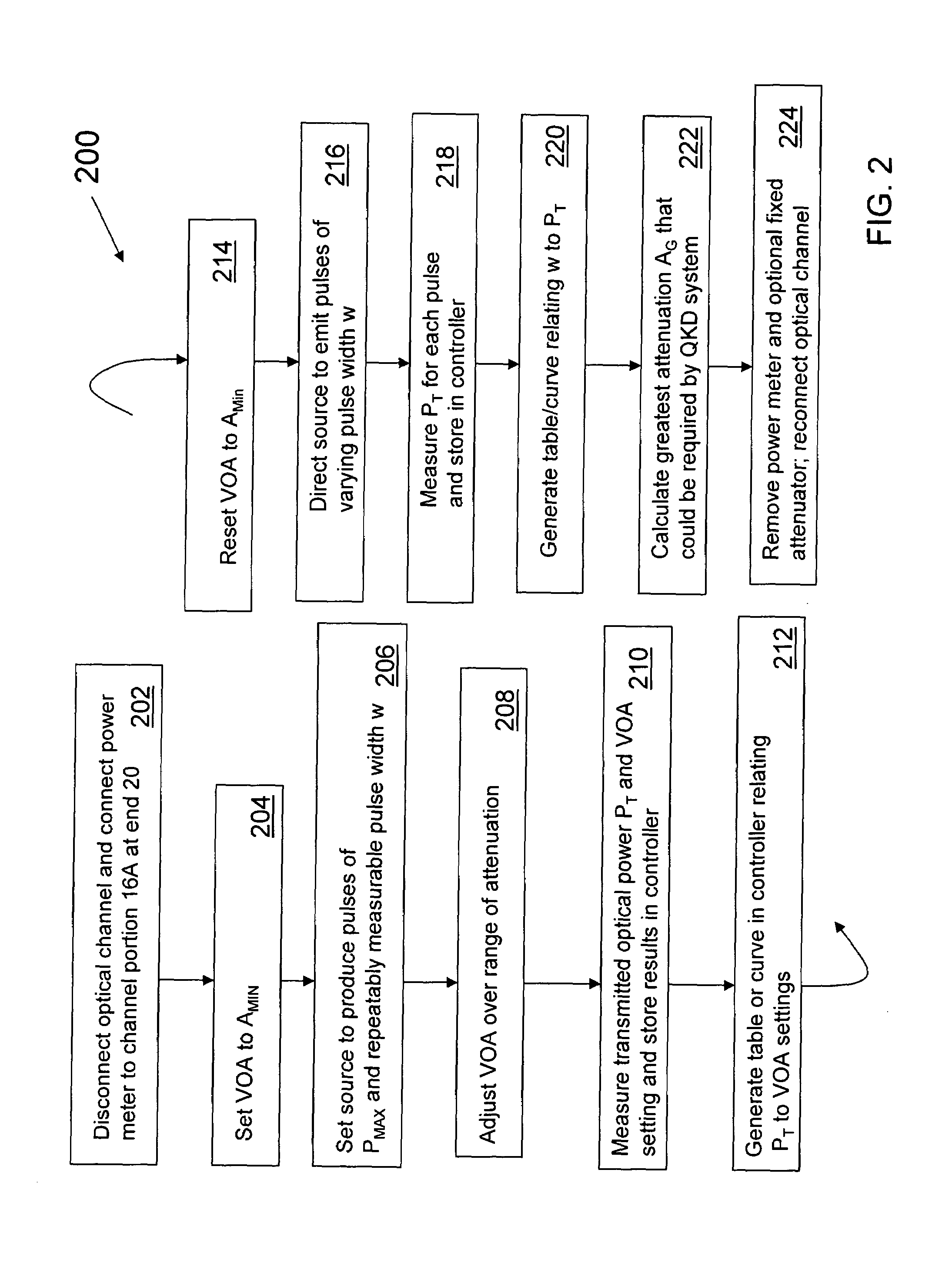
[0017]The present invention is a system and method for optical pulse calibration in a QKD system. The systems and methods apply to both one-way and two-way systems. For the sake of convenience, the invention is first described in connection with a one-way system.

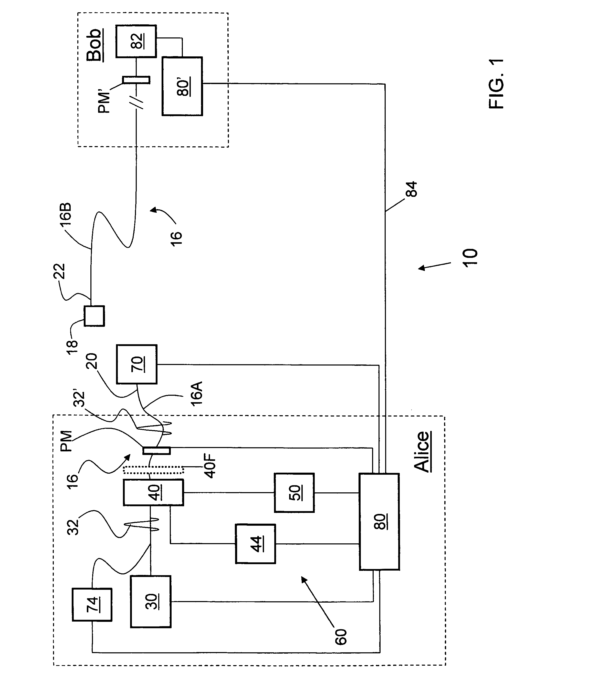
[0018]FIG. 1 is a schematic diagram of a QKD system 10 having a first station Alice and a second station Bob. Alice and Bob are optically couple via an optical channel 16, which may be an optical fiber or free space. Optical channel 16 includes first and second optical channel portions 16A and 16B connected by a connector 18. Channel 16A has an end 20 and channel 16B has an end 22. Connector 18 allows for the optical-channel to be separated downstream of a VOA (discussed below) and accessed in order to perform the calibration procedures of the present invention, as described below. In FIG. 1, optical channel 16 is shown disconnected at coupler 18.

[0019]Alice includes an optical radiation source 30 capable of generating optic...


PUM


Abstract

Methods and systems for generating calibrated optical pulses in a QKD system. The method includes calibrating a variable optical attenuator (VOA) by first passing radiation pulses of a given intensity and pulse width through the VOA for a variety of VOA settings. The method further includes resetting the VOA to minimum attenuation and sending through the VOA optical pulses having varying pulse widths. The method also includes determining the power needed at the receiver in the QKD system, and setting the VOA so that optical pulses generated by the optical radiation source are calibrated to provide the needed average power. Such calibration is critical in a QKD system, where the average number of photons per pulse needs to be very small—i.e., on the order of 0.1 photons per pulse—in order to ensure quantum security of the system.

Description

FIELD OF THE INVENTION[0001]The present invention relates to quantum cryptography, and in particular relates to calibrating the intensity of optical pulses in quantum key distribution (QKD) systems.BACKGROUND OF THE INVENTION[0002]Quantum cryptography involves exchanging messages between a sender (“Alice”) and a receiver (“Bob”) by encoding a plain text message with a key that has been shared between the two using weak (e.g., 0.1 photon on average) optical signals (pulses) transmitted over a “quantum channel.” Such a system is referred to as a quantum key distribution (QKD) system. The security of QKD systems is based on the quantum mechanical principle that any measurement of a quantum system will modify its state. As a consequence, an eavesdropper (“Eve”) that attempts to intercept or otherwise measure the quantum signal will introduce errors into the transmitted signals, thereby revealing her presence. Because only the key is transmitted in a QKD system, any information about the...

Claims


Application Information

Patent Timeline
Patent Type & Authority Patents(United States)
IPC IPC(8): H04L9/00H04L9/08
CPCH04B10/70H04L9/0858
Inventor VIG, HARRY N.TRIFONOV, ALEXEI
Owner MAGIQ TECH INC
Why Eureka
Try Eureka