
Image forming apparatus with processing unit that can be removed from the image forming apparatus without removing exposing devices

Active Publication Date: 2007-07-10
BROTHER KOGYO KK
View PDF44 Cites 25 Cited by
  • Summary
  • Abstract
  • Description
  • Claims
  • Application Information

AI Technical Summary

Benefits of technology

[0009]The invention thus provides, among other things, a tandem image forming apparatus wherein processing units can be smoothly attached to and detached from the image forming apparatus while providing adequate accuracy in exposing the photosensitive drums.

Problems solved by technology

However, with such placement, the recording head interferes with the replacement of the photosensitive drum.
However, when the recording head moves every time the upper cover opens and closes, there may be variations in the relative position of the recording head to the photosensitive drum, which may cause an image to be deviated.

Method used


Image

  • Image forming apparatus with processing unit that can be removed from the image forming apparatus without removing exposing devices
  • Image forming apparatus with processing unit that can be removed from the image forming apparatus without removing exposing devices
  • Image forming apparatus with processing unit that can be removed from the image forming apparatus without removing exposing devices

Examples


Embodiment Construction

[0031]Embodiments of the invention will be described with reference to the accompanying drawings.

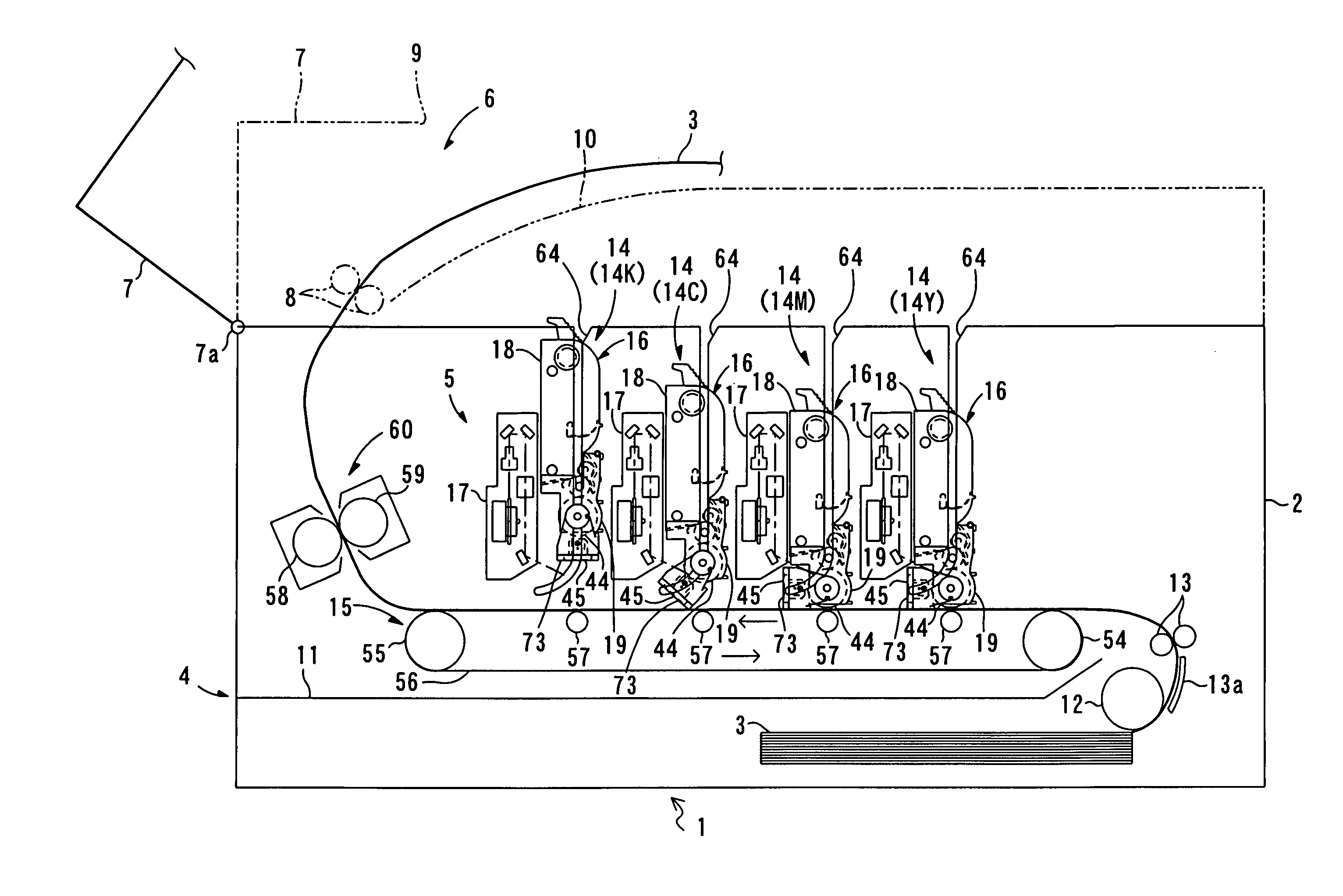
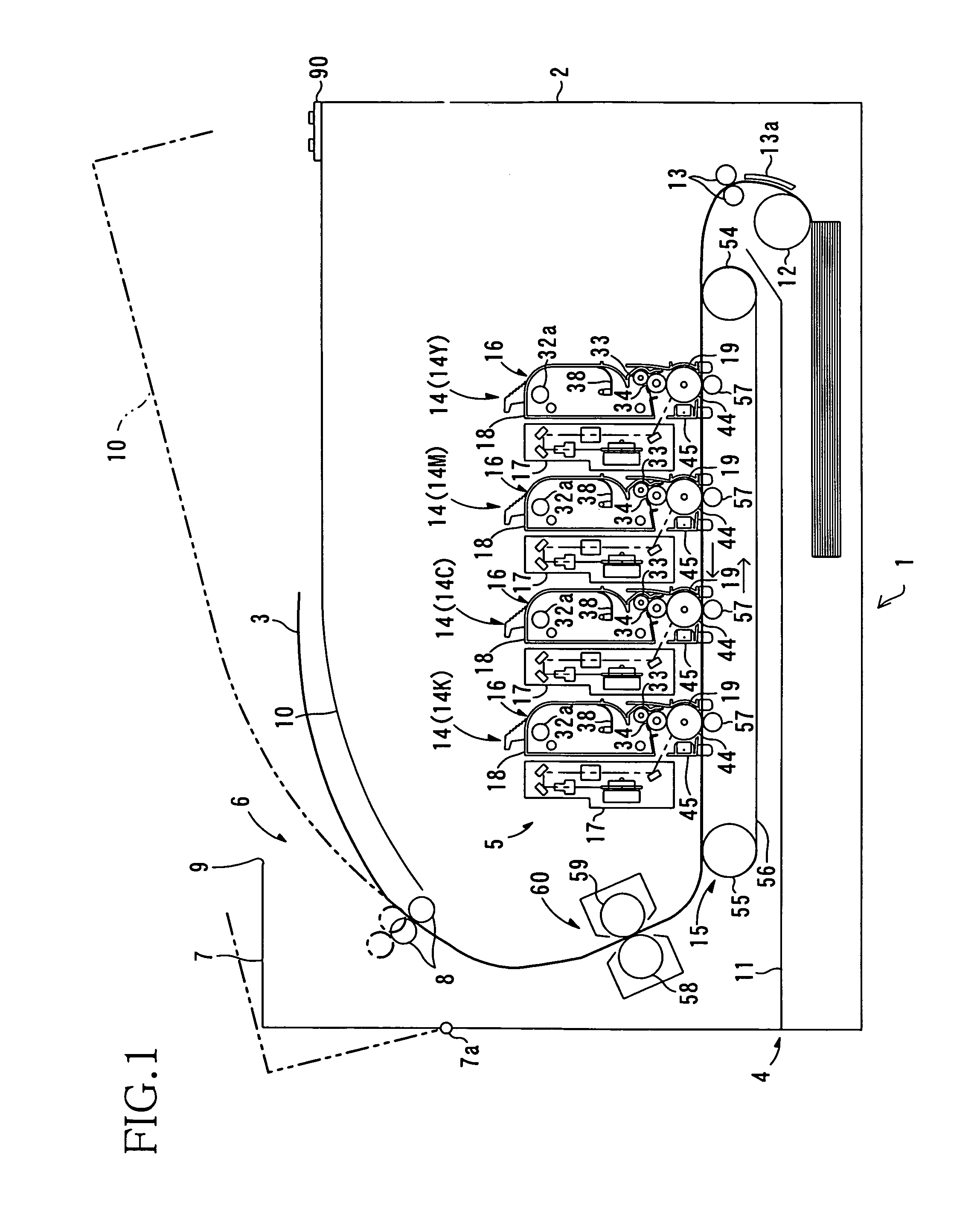
[0032]As shown in FIG. 1, a color laser printer 1 is a so-called tandem color laser printer of a horizontal installation type, wherein four processing portions 14 (described later) are aligned parallel with each other, in a horizontal direction. The color laser printer 1 includes a printer casing 2 as an image forming apparatus body, a sheet feeding portion 4 that feeds a sheet 3 as a recoding medium, an image forming portion 5 that forms an image onto the fed sheet 3, and a sheet discharge portion 6 that discharges the sheet 3 having the image thereon.

[0033]The printer casing 2 has a rectangular box shape when viewed from the side and has no upper wall. The printer casing 2 is provided with a top cover 7 (i.e., cover member) at the opening and at a position opposite to a transfer position where photosensitive drums 44 contact a conveyor belt 56 in the transfer portion 15. The top cover ...


PUM


Abstract

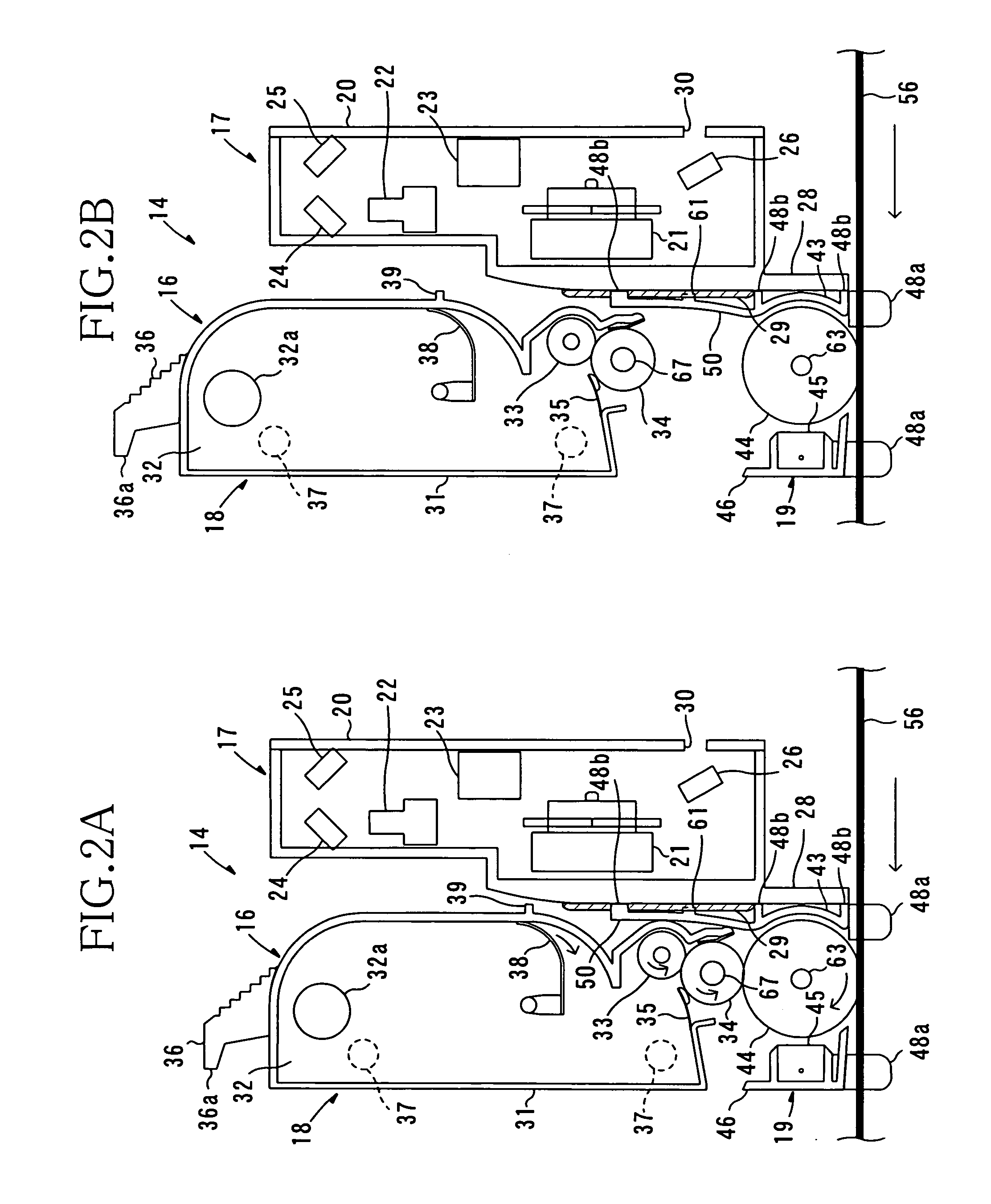
A tandem color laser printer, in which processing units can be smoothly attached to and detached from its casing, is provided while an adequate accuracy of exposure to photosensitive drums is maintained. In the color laser printer, scanning units are fixed to the printer casing. The processing units and the scanning units are alternately aligned and overlapped. A top cover is provided to a side opposite to a transfer position where the photosensitive drums contact a conveyor belt so as to freely open and close with respect to the printer casing. With this structure, the adequate accuracy of exposure by the scanning units can be maintained. The processing units can be attached to and detached from the printer casing via an upper opening of the printer casing defined by the opened top cover. Thus, the processing units can be smoothly attached to and detached from the printer casing without being interfered by the scanning units.

Description

BACKGROUND OF THE INVENTION[0001]1. Field of Invention[0002]The invention relates to an image forming apparatus such as a color laser printer.[0003]2. Description of Related Art[0004]As an electrophotographic color laser printer, there exists a so-called tandem color laser printer that includes a plurality of processing units, each of which has a developing agent hopper, a developing roller and a photosensitive drum, with respect to toner colors of yellow, magenta, cyan, and black.[0005]In the above tandem color laser printer, toner images of the respective colors are formed on the respective photosensitive drums at almost the same instant by which toner particles stored in the developing agent hopper are supplied onto the photosensitive drum by the developing roller in each of the processing units. Therefore, a color image can be formed at a speed that is almost the same as an image forming speed of a monochrome laser printer.[0006]As the above tandem color laser printer, Japanese ...

Claims


Application Information

Patent Timeline
IPC IPC(8): G03G15/00G03G15/01G03G15/08G03G21/16G03G21/18
CPCG03G21/1853G03G15/0194G03G2221/183G03G2215/0119
Inventor ISHII, MASAHIRO
Owner BROTHER KOGYO KK
Learn More