
Power tool with battery power supply

a battery power supply and power tool technology, applied in the field of power tools, can solve the problems of reducing the resiliency of springs, the difficulty of the battery package being detached from the power tool, and the complicated mechanical structure of the battery package, and achieve the effect of durable and reliable attachment mechanism of the battery packag

Inactive Publication Date: 2007-07-17
NANJING CHERVON IND
View PDF190 Cites 44 Cited by
  • Summary
  • Abstract
  • Description
  • Claims
  • Application Information

AI Technical Summary

Benefits of technology

The solution provides a reliable, durable, and easy-to-use mechanism for attaching and detaching the battery package, maintaining functionality over time without the complications of mechanical spring degradation.

Problems solved by technology

During the operating of a power tool, unavoidable vibrations require an especially tight connection between the battery package and the power tool to prevent the connection from being loosened.
However, the tight connection between the battery package and the power tool makes it difficult for the battery package to be detached from the power tool.
One disadvantage of such a mechanism is its complicated mechanical structure.
Furthermore, over time, the resiliency of the springs may be reduced with the result of the reduced function of the resilient pushing mechanism due to degradation of material properties over time and as a result of continued use.

Method used


Image

  • Power tool with battery power supply
  • Power tool with battery power supply
  • Power tool with battery power supply

Examples


Embodiment Construction

[0015]While this invention is susceptible of embodiments in many different forms, there is shown in the drawings and will herein be described in detail preferred embodiments of the invention with the understanding that the present disclosure is to be considered as an exemplification of the principles of the invention and is not intended to limit the broad aspect of the invention to the embodiments illustrated.

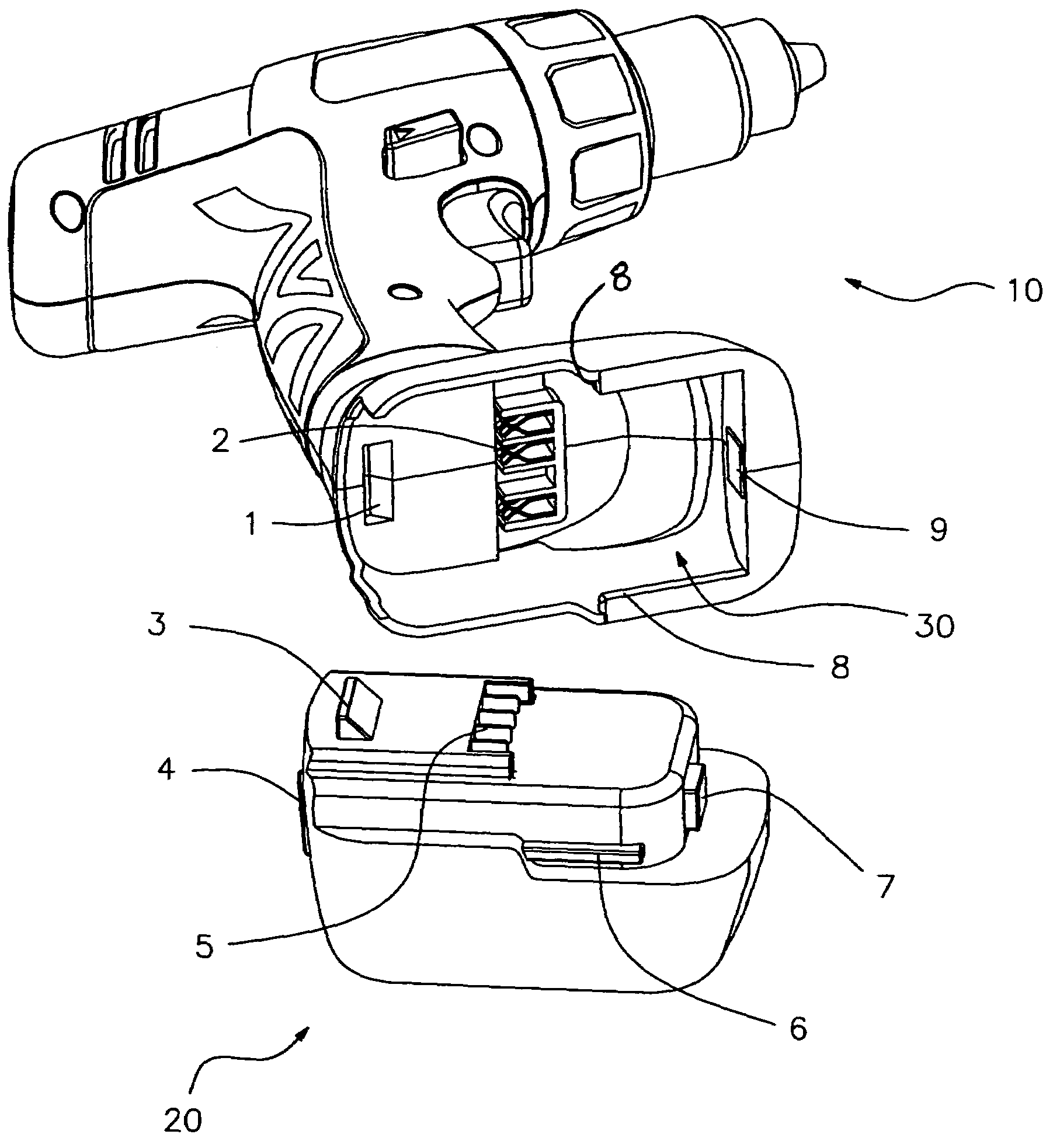
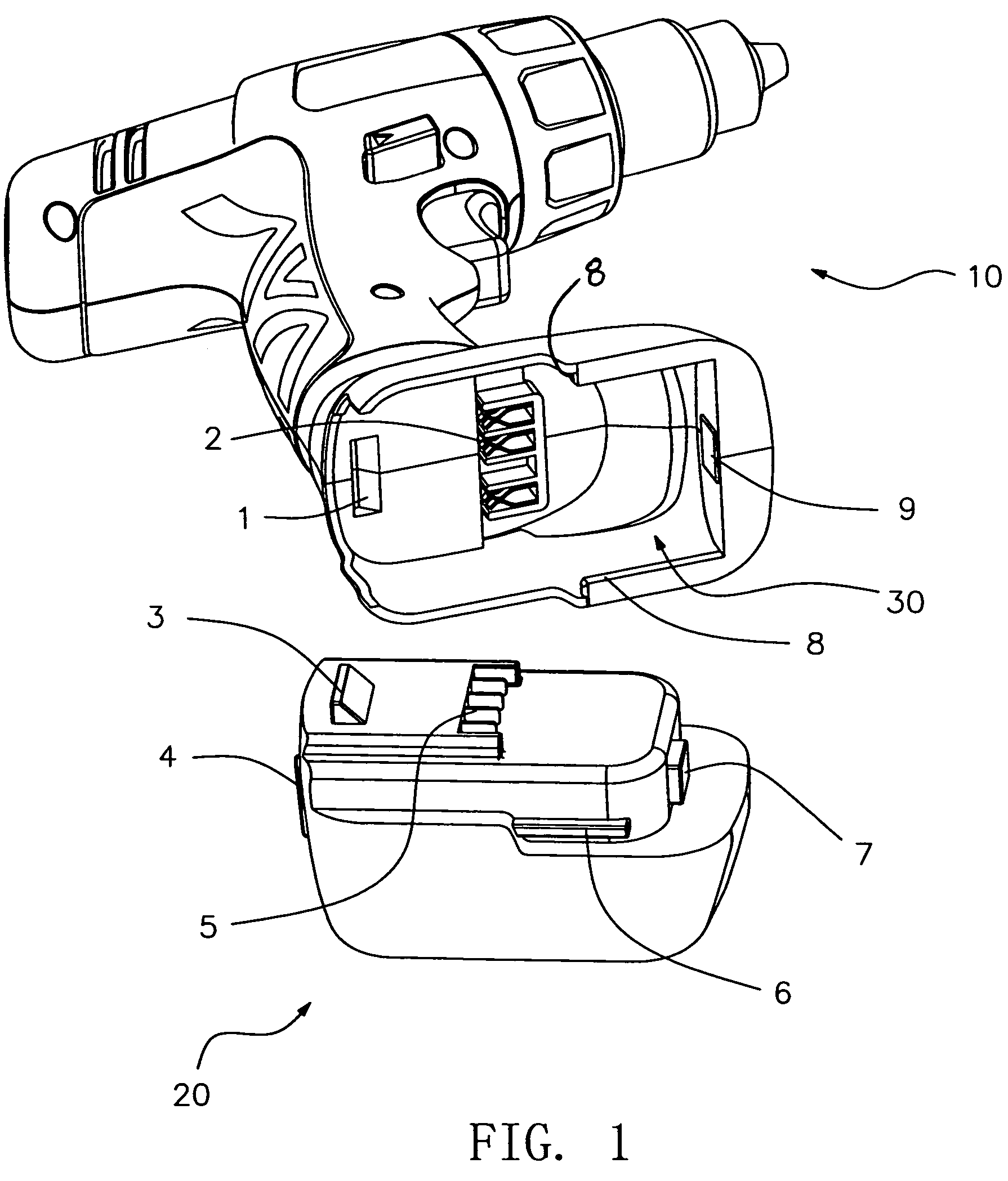
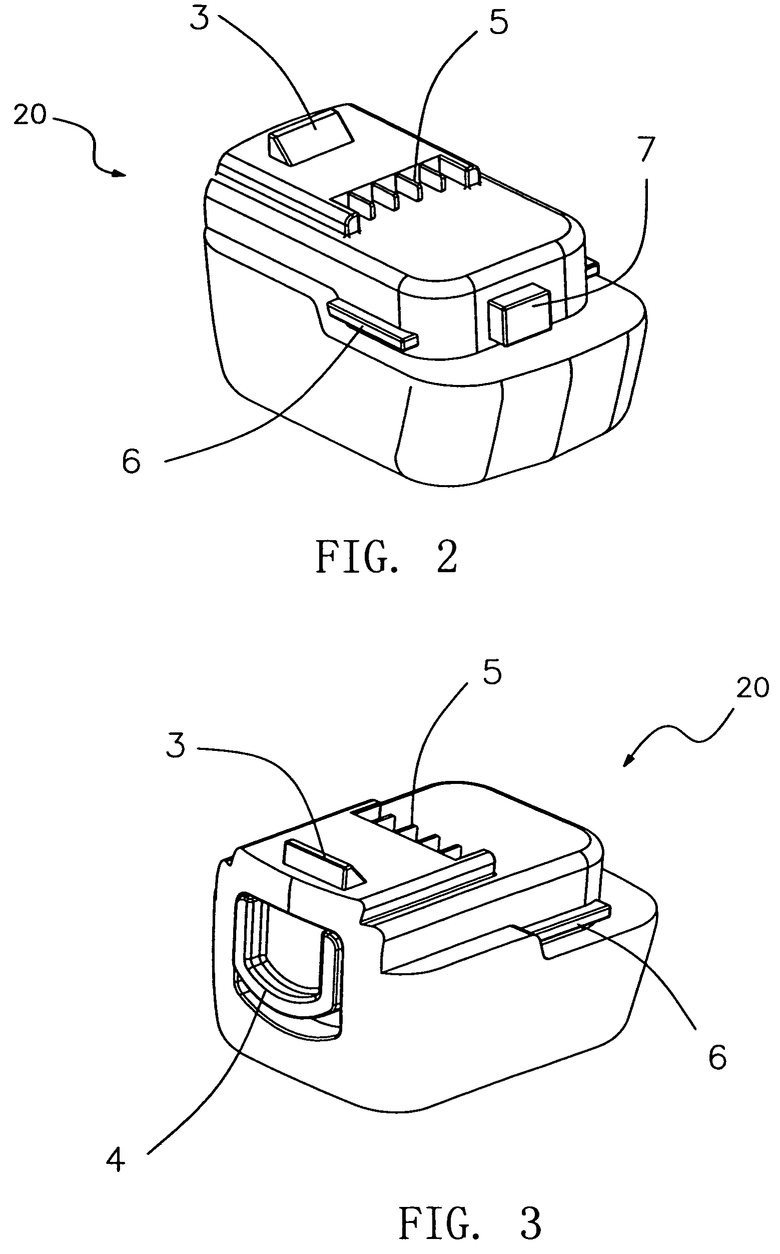
[0016]FIGS. 1 to 3 schematically show an electric drill according to a preferred embodiment of the present invention. However, it should be understood the battery power supply attachment mechanism of the present invention could be utilized with any suitable power tool. The power tool comprises a main body 10 and a detachable battery package 20. The main body 10 houses a motor (not shown) which is powered by the detachable battery package 20. The main body 10 comprises a securing frame 30 formed thereon or connected thereto for receiving and containing at least a portion of the ...


PUM

PropertyMeasurementUnit
repulsive forceaaaaaaaaaa
polarityaaaaaaaaaa
forceaaaaaaaaaa

Abstract

The present invention relates to a power tool with battery power supply comprising a main body and a detachable battery package which are connected with each other via a securing frame and a locking assembly. The securing frame includes a guiding device, an locking / unlocking button located on one of the main body and the battery package. An electrical connection is provided between a motor in the main body and the battery package, and includes a plurality of electrode connectors and corresponding electrode contact tabs. A mechanism for creating a non-mechanical force is located between the main body and the battery package for pushing the battery package out of the securing frame. With such a mechanism, when the battery package is required to be replaced by another one or detached for charging, it is merely necessary to press the unlocking button downward, and the battery package then automatically slides out of the securing frame via the effect of the force so as to facilitate detaching the battery package from the main body of the power tool.

Description

CROSS-REFERENCE TO RELATED APPLICATIONS[0001]This application claims priority under 35 U.S.C. § 119 to Chinese Application No. 200520069691.7, filed on Jan. 10, 2005.FEDERALLY SPONORED RESEARCH AD DEVELOPEMENT[0002]None.TECHNICAL FIELD[0003]The invention relates to a power tool with a detachable power supply package and, more particularly, to the manner for attaching and detaching the power supply package of the power tool.BACKGROUND OF THE INVENTION[0004]It is common for a power a power tool to be provided with battery packages. During the operating of a power tool, unavoidable vibrations require an especially tight connection between the battery package and the power tool to prevent the connection from being loosened. However, the tight connection between the battery package and the power tool makes it difficult for the battery package to be detached from the power tool.[0005]A cordless electric drill with a resilient mechanism for detaching the battery package from a power tool i...

Claims


Application Information

Patent Timeline
Patent Type & Authority Patents(United States)
IPC IPC(8): H02J7/00B25F3/00H01M50/202H01M50/244H01M50/247H01M50/296
CPCH01M2/1022Y02E60/10H01M50/247H01M50/202H01M50/296H01M50/244
Inventor WU, SHUMING
Owner NANJING CHERVON IND
Learn More