Positioning device for furniture

a positioning device and furniture technology, applied in the direction of chairs, vehicle components, vehicle arrangements, etc., can solve the problems of mechanism wobble or uneven path, user's uncomfortable position adjustment, and many prior positioning devices complex and expensive to manufacture, so as to minimize abrupt acceleration of the strut

Inactive Publication Date: 2007-07-17
TORNERO LINO E
View PDF51 Cites 44 Cited by
  • Summary
  • Abstract
  • Description
  • Claims
  • Application Information

AI Technical Summary

Benefits of technology

[0008]The aforesaid and other objectives are realized by providing a positioning device for ease in adjustability and positioning, for use in furniture. In the preferred embodiment of the invention, the user has only to provide an external force upon the strut of the positioning device to cause the strut to easily and precisely telescope within a mounting member. The positioning device is also provided with means for limiting the displacement of the strut relative to the mounting member so the strut can only telescope or slide for a limited distance while remaining at all times in sliding but controlled engagement within the mounting member.
[0010]The positioning device regulates the speed of movement by a deformable member inserted so as to contact both the strut and mounting member simultaneously to provide friction during motion. As a result, the force required to telescope the members can be made to remain substantially constant along the entire movement, thus minimizing abrupt accelerations of the strut. Alternately the positioning device may be provided with a deformable member for selective engagement in a variety of discrete positions.

Problems solved by technology

Certain prior devices utilize external knobs, clamps, and levers that are often difficult or hazardous to operate, and often cause the user to assume uncomfortable positions to adjust them.
Many prior positioning devices are complex and expensive to manufacture.
In some cases, precision and smooth operation is sacrificed in favor of economy, causing such mechanisms to wobble or move in uneven paths during adjustment and operation.
Some make excessive noise, or bind and cease to function altogether.
In other cases, such as mechanisms that provide for discrete adjustment positions selectable by the use of levers, the user often struggles trying to find the most desired position.

Method used


Image

  • Positioning device for furniture
  • Positioning device for furniture
  • Positioning device for furniture

Examples


Embodiment Construction

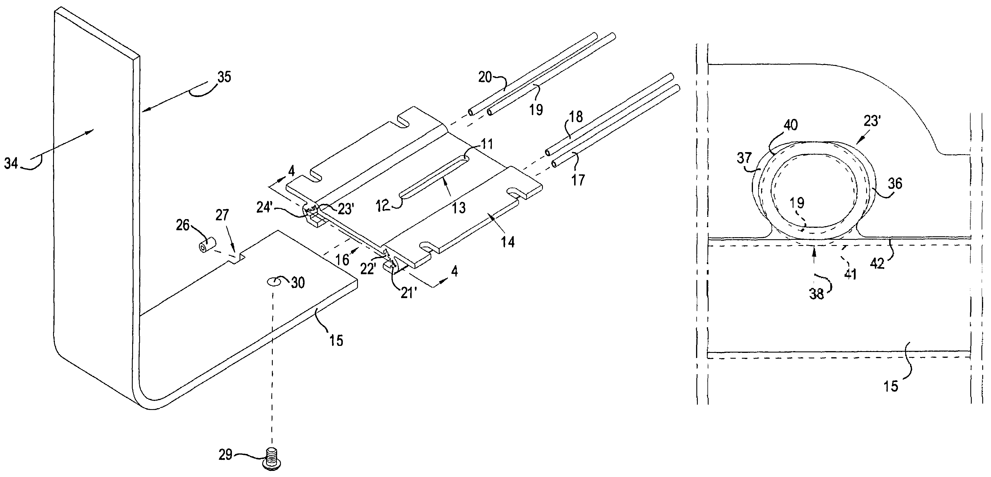
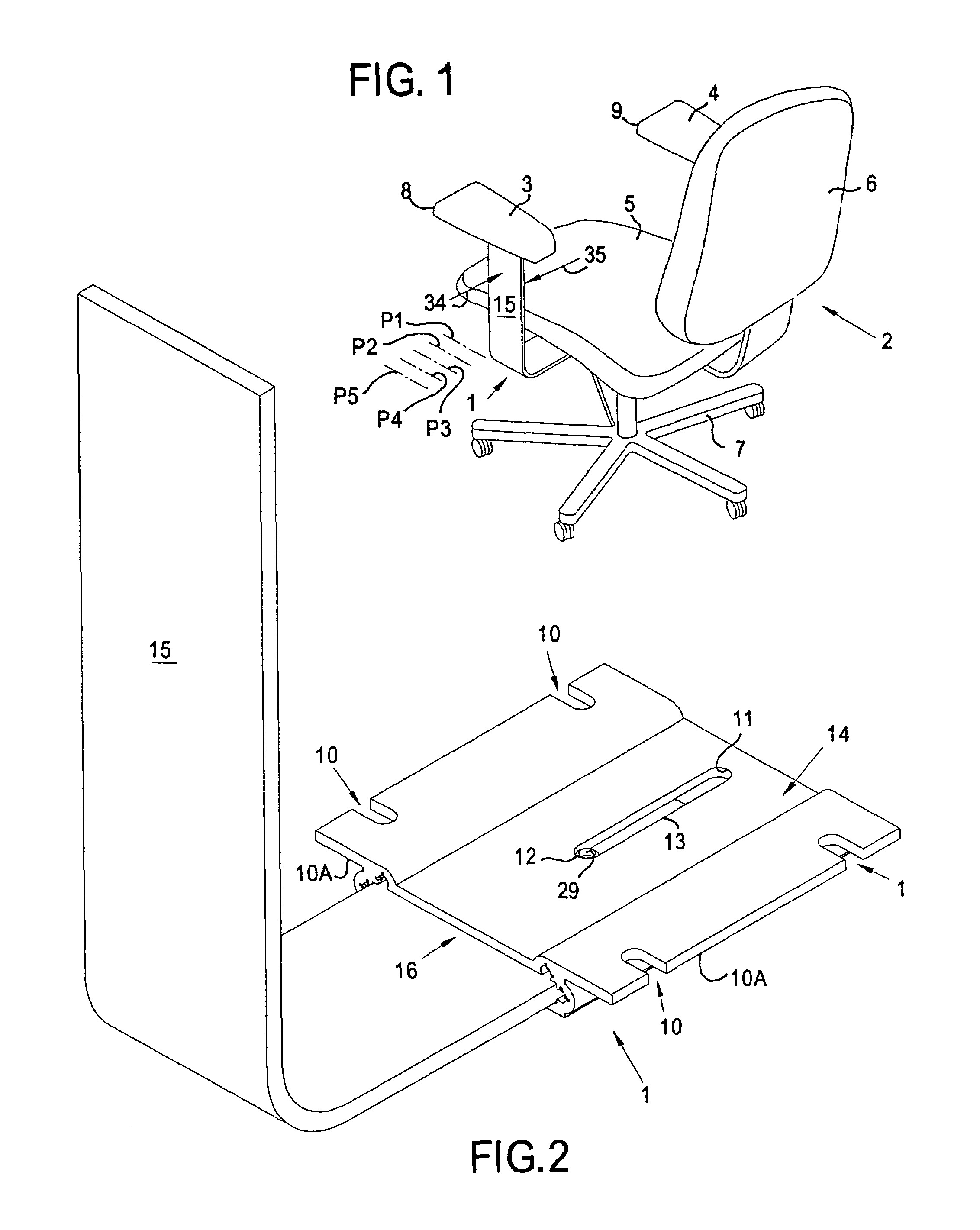
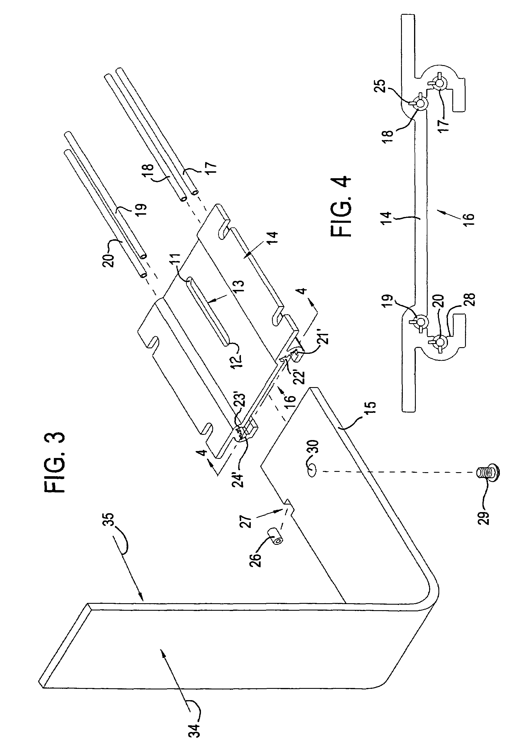
[0031]For a better understanding of the invention and its operation, turning now to the drawings, FIG. 1 shows standard chair 2 having preferred positioning device 1 installed thereon. Chair 2 comprises arms 3 and 4, seat 5, back 6, base 7 and arm pads 8 and 9. Shown enlarged in FIG. 2, positioning device 1 comprises mounting member 14 having mounting slots 10, flanges 10A, slot 13 having ends 11 and 12, and cavity 16 for slidably receiving strut 15. Mounting member 14 also includes channels 21′-24′ for receiving deformable tubular guide members 17-20 shown in FIG. 3. Two positioning devices 1 are assembled as shown in FIG. 2, one for each of chair arms 3 and 4. Arms 3 and 4 are then mounted to the underside of chair seat 5 by means of mounting slots 10 in mounting flanges 10A with screws (not seen). Positioning devices 1 allow a chair occupant (not shown) to easily, manually horizontally position arms 3 and 4 relative to chair seat 5 in any of an infinite number of positions illust...


PUM


Abstract

The invention herein allows for manually positioning telescoping members relative to each other in a variety of positions within a given range of motion such as for movable chair backs or arms. A strut is engaged with and telescopically slides in a mounting member while deformable guide members provide for frictional engagement of the strut within the mounting member. A détente limits the range of motion of the strut relative to the mounting member. The détente comprises a stud or tab which engages a slot in the mounting member.

Description

FIELD OF THE INVENTION[0001]The invention herein pertains to devices that provide positioning of structural members relative to one another and which are particularly useful in the furniture industry. Uses may include adjustable chair arms and other components to provide ergonomic comfort.DESCRIPTION OF THE PRIOR ART AND OBJECTIVES OF THE INVENTION[0002]Positioning mechanisms for chair arms, backs, seats and the like have long been known in the industry. U.S. Pat. Nos. 4,613,106; 4,616,812; 4,720,068: 4,749,230; 4,930,840; 5,338,133; 5,388,892; 5,586,811; 5,660,442 and 5,951,107 demonstrate a few of the known adjustable mechanisms that are commonly used. Certain prior devices utilize external knobs, clamps, and levers that are often difficult or hazardous to operate, and often cause the user to assume uncomfortable positions to adjust them. Today's ergonomic requirements in the market place and furniture industry demand user friendly, easily adjustable mechanisms that permit rapid a...

Claims


Application Information

Patent Timeline
Patent Type & Authority Patents(United States)
IPC IPC(8): A47C7/54
CPCA47C1/03A47C1/0307
Inventor TORNERO, LINO E.
Owner TORNERO LINO E
Why Eureka
Try Eureka