
Grid construction for a fluidized bed reactor

Inactive Publication Date: 2007-07-17
FOSTER WHEELER ENERGIA OY
View PDF13 Cites 28 Cited by
  • Summary
  • Abstract
  • Description
  • Claims
  • Application Information

AI Technical Summary

Benefits of technology

[0009]An object of the present invention is thus to provide an improved grid construction wherein the drawbacks mentioned above have been minimized.
[0010]A special object of the present invention is to provide a durable grid construction with improved coarse material discharge.
[0011]Another object of the present invention is to provide a grid construction, in which the sticking of material to the fluidizing air nozzles has been minimized.

Problems solved by technology

The accumulation of the coarse material may be a problem especially when solid fuels rich in non-combustible material, such as stones or scrap iron, are processed in the reaction chamber, or when the process generates such coarse material, as, for example, ash agglomerations.
A conventional material discharge channel or a few material outlet pipes placed at the bottom of a reactor chamber are, however, often not sufficient for efficient removal of coarse material, as random movement generated by the fluidizing air is not capable of transporting heavy or unfavorably-shaped pieces horizontally for long distances.
Also, the migration of material along the bottom of the reactor chamber is especially hampered when the bottom has upwardly projecting air nozzles or other irregularities, to which the coarse material may stick.
However, separate air nozzles are prone to erosion, and coarse material may stick into the nozzles.
The problem with these solutions may, however, be abrasion of the nozzles and regions in their vicinity, caused by the moving material and by the transport air being fed at a high velocity.
It is also difficult to ensure an even air feed over the entire grid area due to the different bed pressures at various nozzles, at least when the bottom has significant level differences.
However, the construction provides a highly varying flow velocity field at the bottom, and thus, there is a risk of erosion or accumulation of coarse particles in low velocity areas.

Method used


Image

  • Grid construction for a fluidized bed reactor
  • Grid construction for a fluidized bed reactor
  • Grid construction for a fluidized bed reactor

Examples


Embodiment Construction

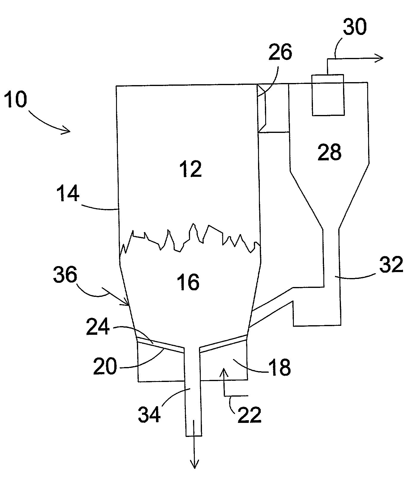
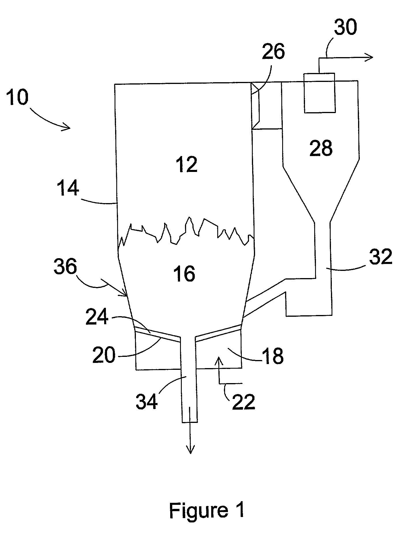
[0041]FIG. 1 depicts, in vertical cross section, a fluidized bed reactor 10 with a reaction chamber 12 defined by vertical walls 14 in which a fluidized bed 16 of solid particles is maintained. In a lower portion of the reactor 10, under the reaction chamber 12, is a windbox 18. Between the reaction chamber 12 and the windbox 18 is positioned a grid 20 for suspending the fluidized bed 16 in the reaction chamber. The bed 16 is maintained in a fluidizing state by introducing fluidizing gas through fluidizing gas inlet means 22 to the windbox 18 from where the gas is injected to the reaction chamber 12 through nozzle lines 24 disposed in the grid 20.

[0042]FIG. 1 shows a fast fluidized bed reactor, in which the velocity of the fluidizing gas in the reaction chamber 12 is so high that solid particles, such as solid fuel, possible absorbents and inert bed material, are entrained with the fluidizing gas to the upper part of the reaction chamber 12 and through an outlet opening 26 to a cycl...


PUM


Abstract

A grid construction for a fluidized bed reactor, the reactor including a reaction chamber defined by substantially vertical walls, in which a fluidized bed of solid particles is maintained, and a windbox under the reaction chamber, in a lower portion of the reactor. The grid construction is positioned between the reaction chamber and the windbox and includes (a) multiple continuous nozzle lines for distributing fluidizing gas from the windbox into the reaction chamber, for suspending the fluidized bed in the reaction chamber, and (b) continuous trenches between the nozzle lines. The nozzle lines include multiple gas outlets, having a main gas flow direction, at side faces of said nozzle lines, for directing fluidizing gas jets towards an adjacent trench.

Description

BACKGROUND OF THE INVENTION[0001]The present invention relates to a grid construction for a fluidized bed reactor and a method of using such a grid construction for removing coarse material from the bottom of a fluidized bed reactor. More particularly, the present invention relates to a durable grid construction optimized for reliable and efficient removal of coarse material from a fluidized bed reactor.[0002]Fluidized bed reactors comprise a reaction chamber, defined by vertical walls, having a fluidized bed of solid particles maintained therein, a windbox in a lower portion of the reactor under the reaction chamber, and a grid construction between the reaction chamber and the windbox for supporting the fluidized bed in the reaction chamber. In the grid construction, there are typically means, such as nozzles, for distributing fluidizing air or other gas into the reaction chamber from the windbox.[0003]Fluidized bed reactors are used for different processes, such as combustion or g...

Claims


Application Information

Patent Timeline
IPC IPC(8): B01J8/44B01J8/38B01J10/00F23C10/20F27B15/10
CPCB01J8/388B01J8/44F23C10/20B01J8/02
Inventor MYOHANEN, KARITAIBI, FRANKVILOKKI, HARRI
Owner FOSTER WHEELER ENERGIA OY
Features
  • Generate Ideas
  • Intellectual Property
  • Life Sciences
  • Materials
  • Tech Scout
  • Unparalleled Data Quality
  • Higher Quality Content
  • 60% Fewer Hallucinations
Learn More