
Miter bar

a technology of miter bars and ring heads, which is applied in the field of miter bars, can solve the problems of increased saw noise, unsatisfactory cutting, and threat of workpiece kickback, and achieve the effect of accurate setting up, clean, safe and accurate cutting

Inactive Publication Date: 2007-07-17
REILLY PAUL J
View PDF5 Cites 25 Cited by
  • Summary
  • Abstract
  • Description
  • Claims
  • Application Information

AI Technical Summary

Benefits of technology

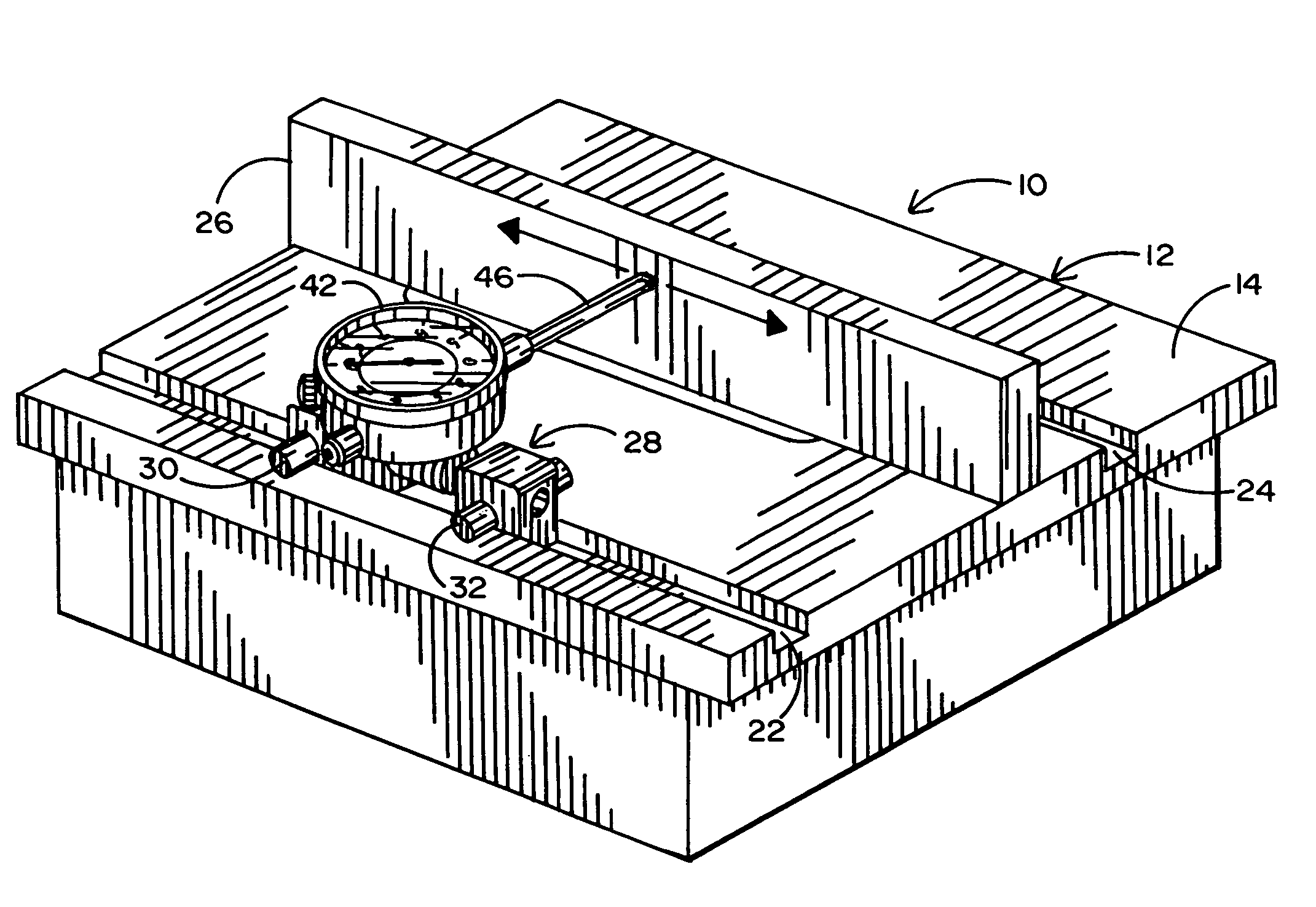
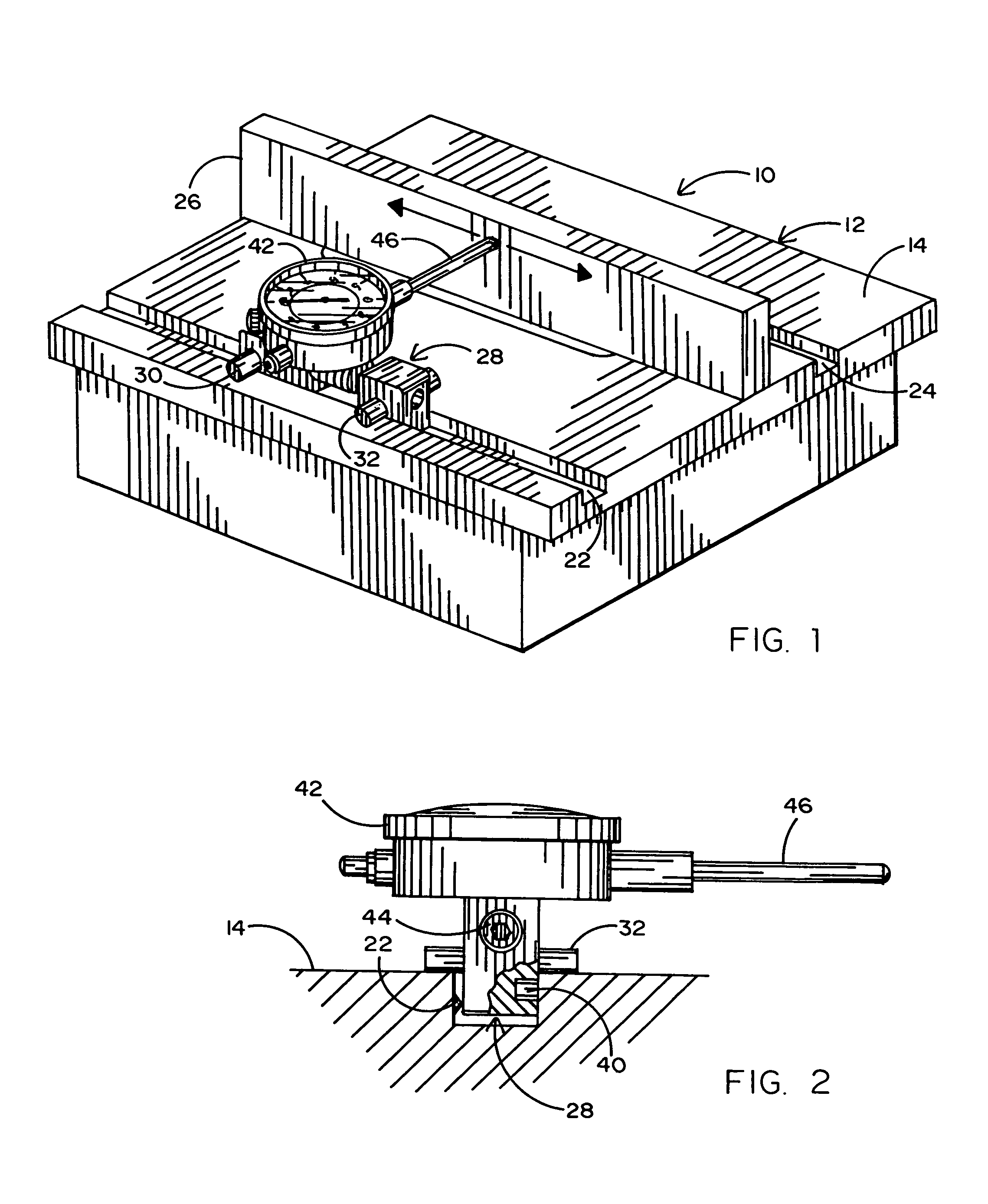
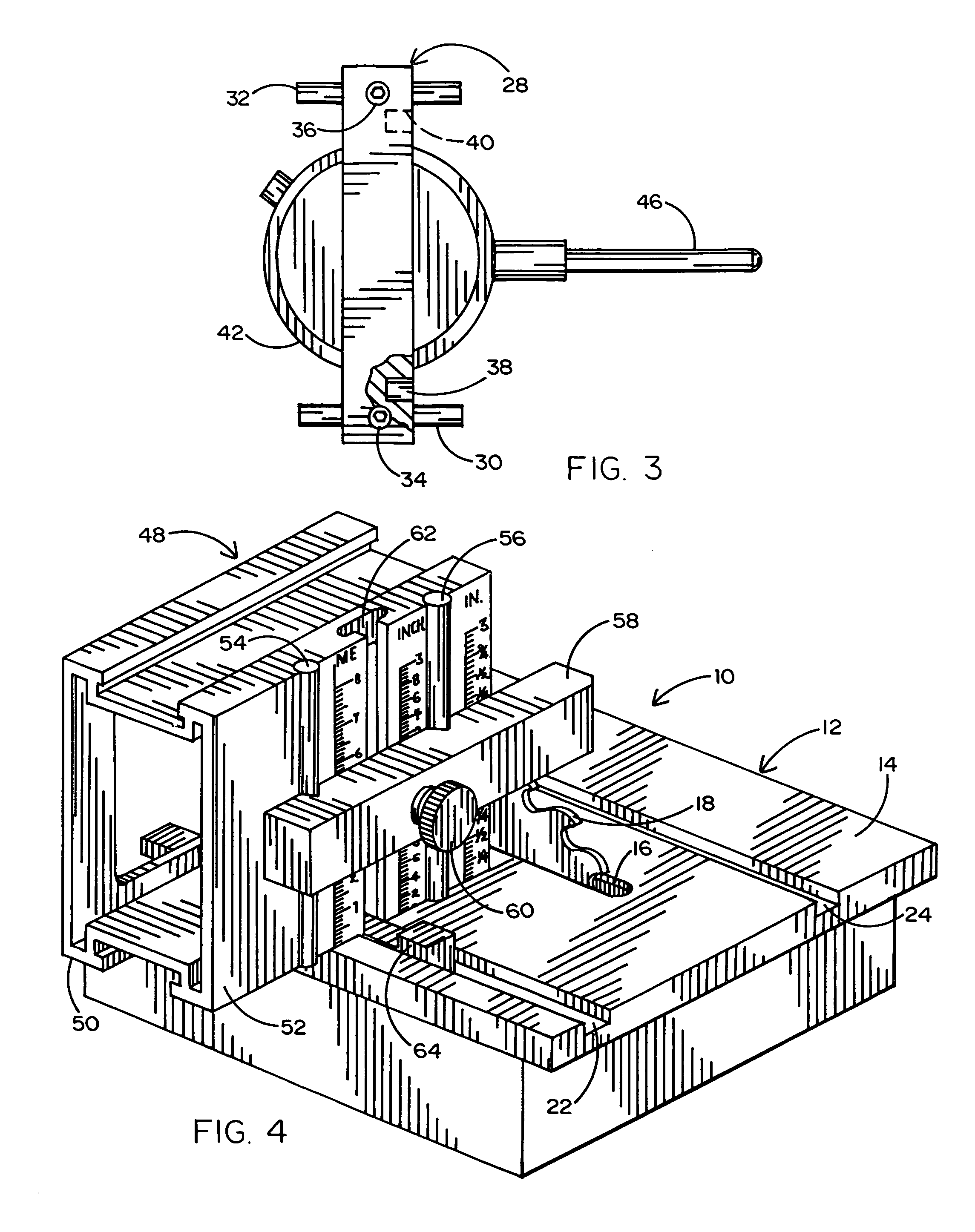
[0006]It is, thus, a purpose and advantage of this invention to provide a magnetic miter slot bar which is part of an alignment system that assures correct alignment between the miter slot, saw blade, rip fence and miter gages in table saws, top saws and the like so that the saws can be accurately set up to make clean, safe and accurate cuts.
[0009]It is another purpose and advantage of this invention to provide an alignment system which includes a slide bar which fits into the miter slot of a table and fits within the slot and can travel the full length of the miter slot with precision so as to ensure accurate measuring readings from the miter slot to the plane of the saw blade.

Problems solved by technology

This is undesirable for several reasons, including the fact that smooth cutting is not achieved.
In addition, saw noise is increased.
Another important reason is that there is a threat of kickback of the workpiece as it is being cut.
In the past, setting up the table saw has been very time-consuming and filled with a large amount of trial and error.
However, machinery of this type does not stay in adjustment because the machinery is hard-working and is subject to heavy loads and pounding from the lumber which it cross-cuts, rips or dados.

Method used


Image

  • Miter bar
  • Miter bar
  • Miter bar

Examples


Embodiment Construction

[0019]This invention is directed to an alignment system which is particularly useful for table saws and the like. The alignment system assures correct alignment between the miter slot, rip fence and miter gages with respect to the plane of the saw blade. It is particularly useful in table saws and the like so that the saws can be accurately set up and make clean, safe, accurate cuts. The system is particularly useful with any machinery which has a miter slot in the table.

[0020]Table saw 10, seen in FIGS. 1 and 4, has a saw table 12 which has a planar top surface 14. There is a saw slot 16 in the table. A spindle below the table top defines an axis. Mounted on this spindle is saw blade 18. It is the spindle axis which defines the line to which all relevant surfaces are related. Sometimes the spindle is tiltable with respect to the top surface of the saw table, but for the purpose of this discussion, this preferred embodiment of the magnetic miter slot bar will describe the situation ...


PUM

PropertyMeasurementUnit
magneticaaaaaaaaaa
angleaaaaaaaaaa
frictionaaaaaaaaaa

Abstract

The saw table guide bar has magnets thereon so that when it is inserted into the slot in an iron saw table it is urged to slide along the side of the slot. The magnetic saw table guide bar is used to support various measuring devices and overcomes measuring difficulties resulting from table slots of varying width.

Description

CROSS REFERENCE[0001]This application relies for priority on the Provisional Application entitled “Magnetic Miter Slot Bar,” filed Apr. 7, 2004, Ser. No. 60 / 560,776.BACKGROUND OF THE INVENTION[0002]Many woodworking and other machines have a spindle rotating on an axis. This axis is used as a reference for setting the various tools guides and surfaces on the machine. On a table saw, a circular saw blade is mounted on the spindle. This blade is flat and lies in a plane at a right angle to the spindle axis. The table saw has a ferrous table with a saw slot therein. The saw blade extends up through the saw slot, to extend above the table surface. For most purposes, the table surface is at a right angle to the plane of the saw blade so that square cuts are made. The workpiece has a flat surface which lies against the plane of the table surface. Moving the workpiece past the blade makes the cut surface at a right angle to the table surface, as long as the spindle is positioned correctly. ...

Claims


Application Information

Patent Timeline
Patent Type & Authority Patents(United States)
IPC IPC(8): B27G23/00
CPCB23D59/002B27B27/00Y10S33/01
Inventor REILLY, PAUL J.
Owner REILLY PAUL J
Learn More