Heat transfer device

a heat transfer device and heat transfer technology, applied in indirect heat exchangers, lighting and heating apparatuses, cooling/ventilation/heating modifications, etc., can solve the problems of difficult to form the liquid film of working fluid on the outer circumferential, and insufficient flow rate of working fluid back to the stack, etc., to achieve excellent heat transport performance, facilitate reflux of fluid, and efficient heat transport

Inactive Publication Date: 2007-07-24
FUJIKURA LTD
View PDF14 Cites 58 Cited by
  • Summary
  • Abstract
  • Description
  • Claims
  • Application Information

AI Technical Summary

Benefits of technology

[0013]It is an object of the present invention to improve heat transporting characteristics of a heat transfer device, in which a wick having porous structured stacks or cones, is arranged at the bottom portion of a container wherein a fluid is encapsulated. More specifically, the object of the invention is to flow the fluid back to stacks or cones intensively.
[0019]The external side of the bottom face of the container is in contact with a heat source. Specifically, the heat is transmitted to the wick on the bottom face of the container so that the fluid which is absorbed in the wick is evaporated. The evaporation of the fluid takes place principally at a liquid film formed on the lower side of the outer circumferential face of the projections of the wick (i.e., the portions of the projections which are in the vicinity of the base layer). Accordingly, the evaporated fluid ascends between the individual projections and contacts with the upper face side of the container, i.e., a heat radiating portion, so that latent heat is radiated therefrom and the fluid condenses. Thereafter, the fluid is guided by the guide unit to the wick. For example, the fluid may be guided downwardly by the projections arranged on the upper face of the container, and then dropped from the leading end (i.e., lower end) of the projections. The projections of the guide unit may be arranged above the projections of the wick, so that the liquid phase working fluid dropping from the leading end of the projections is fed to the leading end of the projections of the wick. Then, the liquid phase fluid flows down the projections of the wick. Meanwhile, since the projections of the wick are porous structures, the fluid is distributed entirely in the protrusions and the wick by the capillary pumping. For this reason, the fluid flows back to the projections of the wick sufficiently, and the vapor flow and the reflux of the fluid will not collide against each other as a counterflow. Therefore, the heat transport is carried out efficiently so as to attain a heat transfer device in which has excellent heat transport performance. In particular, if the upper face of the container and the lower face of the container, around the projections of the guide unit and the wick, respectively, are inclined toward the projections, it is possible to concentrate the widely dispersing fluid vapor on the wick. As a result, the reflux of the fluid is facilitated so that the heat transport characteristics can be improved.

Problems solved by technology

Thus, there are a number of factors that hinder the evaporation and the flow of the working fluid remains in the traditional thermosiphon.
For this reason, in case the thermosiphon is inclined, or in case a heat flux is large, a flow rate of the working fluid back to the stacks becomes insufficient and this shortage makes it difficult to form the liquid film of the working fluid on the outer circumferential face of the stack.
As a result of this, a heat transporting performance may be degraded.

Method used


Image

  • Heat transfer device
  • Heat transfer device
  • Heat transfer device

Examples


Embodiment Construction

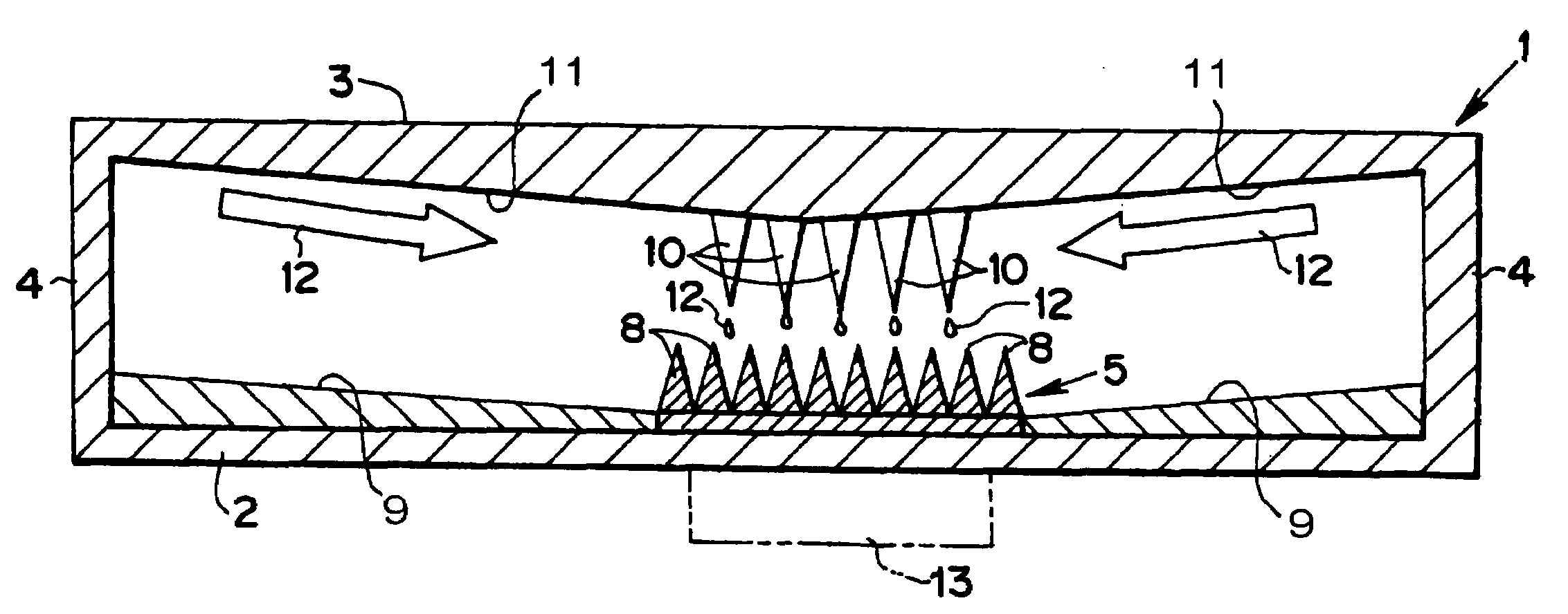
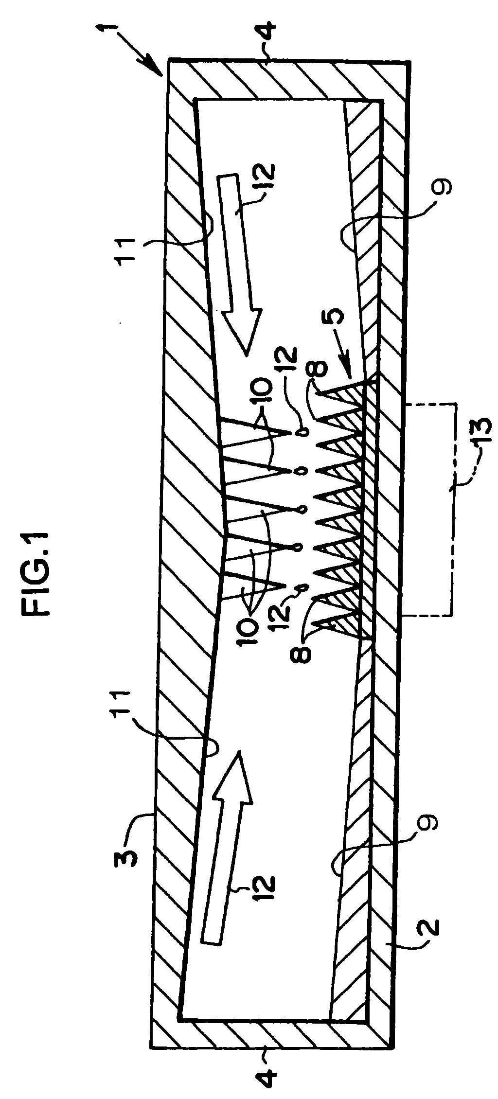
[0032]Hereinafter, exemplary embodiments of the present invention will be described. FIG. 1 shows one example of a heat transfer device according to the invention. The heat transfer device comprises a thin container 1 having a rectangular cross-section. The container 1 is made of a metal having high heat conductivity such as copper, and has a sealed structure such that a bottom plate 2 and an upper plate 3, having large planar dimensions, are combined with side plates 4 having a short height. A porous structured wick 5 is placed in the center of an inner face of the bottom plate 2.

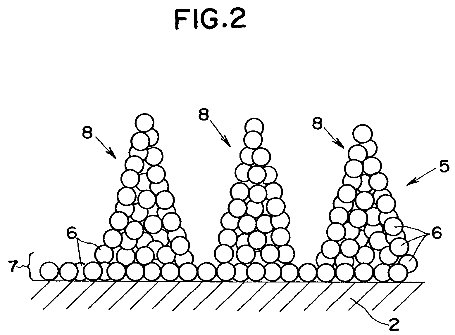
[0033]A structure of wick 5 is illustrated in FIG. 2 in an enlarged scale. The wick 5 is formed into a predetermined shape by consolidating particles 6. The particles 6 have excellent hydrophilicity with a fluid, and are composed of a material which does not react with the working fluid, e.g., a copper particle of several hundred micrometers (e.g., around 200 μm) diameter. Those particles 6 are consolidate...


PUM


Abstract

A heat transfer device including a sealed container, a base layer, formed on the bottom face of the container, and a wick is provided. The wick has a plurality of projections protruding upward from the base layer. A fluid is encapsulated in the container. The heat transfer device further includes a guide unit arranged on an inner face of the container, which guides the liquid to the wick.

Description

BACKGROUND OF THE INVENTION[0001]1. Field of the Invention[0002]The present invention deals generally with heat transfer devices for transporting heat by a condensable working fluid, and more specifically with a heat transfer device, in which a liquid phase working fluid is refluxed mainly by gravity, to a heated portion where the heat is transferred from outside.[0003]2. Discussion of the Related Art[0004]As a heat transfer device, heat pipes are well known in the art, which transport heat in the form of latent heat of a working fluid. In the heat pipes, a non-condensable gas is evacuated from an airtight container, and a condensable fluid such as water or hydrocarbon is encapsulated therein. Therefore, if the heat is transported to a part of the heat pipe from outside while cooling another part, the working fluid is vaporized by the transported heat, and the vapor flows to a cooled part where a temperature and a pressure are low. The vapor releases the latent heat outside of the c...

Claims


Application Information

Patent Timeline
Patent Type & Authority Patents(United States)
IPC IPC(8): F28D15/00H05K7/20
CPCF28D15/046
Inventor MOCHIZUKI, MASATAKATAKENAKA, EIJINGUYEN, THANGKAVIANY, MASSOUD
Owner FUJIKURA LTD
Why Eureka
Try Eureka