Correction-factor determination apparatus and method

a correction factor and apparatus technology, applied in the field of correction factor determination apparatuses and methods, can solve the problems of insufficient evaluation of correction factors such as s, c, and differences in examinations, and achieve the effect of improving the way an image is seen

Inactive Publication Date: 2007-07-24
KK TOPCON
View PDF15 Cites 29 Cited by
  • Summary
  • Abstract
  • Description
  • Claims
  • Application Information

AI Technical Summary

Benefits of technology

[0010]An object of the present invention is to obtain a result close to a subjective value by evaluating, for example, a human observer model from a measurement result obtained by an eye-characteristics measurement apparatus capable of measuring higher-order aberrations, not only when only higher-order aberrations, which correspond to a complete objective correction, are used but also when lower-order aberrations are added, by calculating, for example, a lower-order aberration amount which improves how an image is seen, and by obtaining data of correction factors such as S, C, and A at that time.

Problems solved by technology

However, there may occur differences between subjective values and the objective calculation results of conventional eye-characteristics measurement apparatuses, and insufficient evaluations may be obtained for correction factors such as S, C, and A.
In actual cases, however, the results of the examinations may have differences.

Method used


Image

  • Correction-factor determination apparatus and method
  • Correction-factor determination apparatus and method
  • Correction-factor determination apparatus and method

Examples


first embodiment

4. Correction-Factor Determination Method (First Embodiment)

[0101]FIG. 6 is a flowchart of a correction-factor determination method according to a first embodiment.

[0102]The eye-characteristic measuring apparatus first aligns the X, Y, and Z axes at the pupil position of the eye under measurement (S101). The measuring apparatus next moves the movable block to its origin (S103). For example, the Hartmann plate and the Placido's ring are adjusted to a diopter of zero. The arithmetic part 210 measures eye optical-system data such as the total wavefront aberrations and the Zernike coefficients according to the measured received-light signals {circle around (4)}, {circle around (7)}, and / or (10) (S105). The arithmetic part 210 simulates how the eyesight test chart target is seen and generates target retina image data to calculate correction data (correction factor) (S107). The correction factor includes one of the spherical power (S), the astigmatic power (C), and the angle (A) of the as...

second embodiment

5. Correction-Factor Determination Method (Second Embodiment)

[0176]FIG. 16 is a flowchart of a correction-factor determination method according to a second embodiment. Processes at steps S101 to S105 are the same as in the first embodiment. Then, the arithmetic part 210 calculates correction data for the spherical power (S151). As a specific process thereof, a process described in “4-1. Correction data calculation (spherical power-1)” or “4-2. Correction data calculation (spherical power-2)” can be used.

[0177]Next, the correction-factor setting part 213 of the arithmetic part 210 subtracts a value (in this case, C / 2) corresponding to the astigmatic power C from the obtained spherical power S to specify the initial value of the spherical power S. This is performed because the fact that the astigmatic power is obtained at a position where the back focal line is almost on the retina is taken into account. The value of C may be obtained from the refractive power or the wavefront aberrat...

third embodiment

6. Correction-Factor Determination Method (Third Embodiment)

[0179]FIG. 17 is a flowchart of a correction-factor determination method according to a third embodiment. Processes at steps S101 to S153 are the same as in the second embodiment. Then, the arithmetic part 210 finely adjusts the spherical power (S161), and in step S109, the arithmetic part 210 outputs data in the same way as in the above-described embodiment.

(Spherical-Power Fine Adjustment)

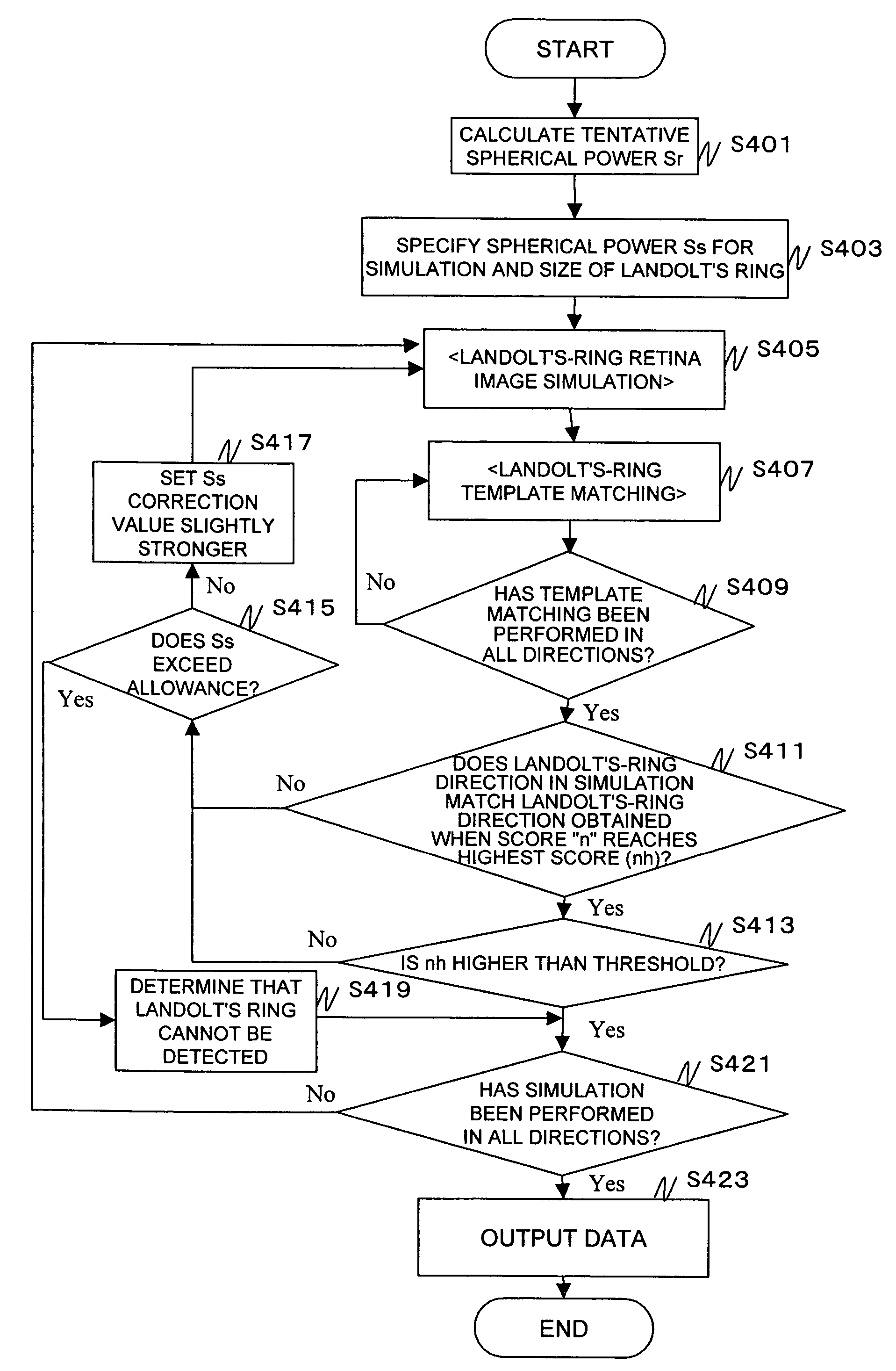
[0180]FIG. 18 shows a flowchart of spherical-power fine adjustment.

[0181]In step S451, as described above, the arithmetic part 210 specifies a spherical power Ss used in simulation according to the calculated S, C, and A. Then, the arithmetic part 210 slightly changes the correction value of Ss (for example, Ss−0.25D, Ss+0.25D) (S601). In this case, slightly changed Ss should fall in Ss±nΔS, a range of change specified in advance. For example, when ΔS=0.2 and “n”=0, 1, 2, and 3, changed values would be Ss−0.6, Ss−0.4, Ss−0.2, Ss, Ss+0.2,...


PUM


Abstract

The low-order aberration leading to better visual acuity is calculated from the results of measurement of an eye characteristic by an eye characteristic measuring instrument that can measure up to the high-order aberration, and data on a correction factor is collected, thereby obtaining a result more approximate to the subjective value. According to at least measurement data representing the wave aberration of the eye being examined (S401, S403), an image data creating unit creates optotype retina image data by conducting simulation of the visual acuity of an optotype (S405), considering the correction factor for refraction correction. A correction factor setting unit sets a correction factor to be given to the image data creating unit (S417). A judging unit judges from the correction opotype retina image data corrected by the correction factor whether or not an adequate correction factor is set (S407 to S421). The correction factor setting unit sets a correction factor on the basis of the results of judgment by the judging unit, and changes the correction factor until the judging unit judge that the correction factor is adequate.

Description

TECHNICAL FIELD[0001]The present invention relates to correction-factor determination apparatuses and methods, and more particularly, to a correction-factor determination apparatus and method for objectively performing measurement close to a subjective value, according to wavefront aberrationsBACKGROUND ART[0002]Conventionally, as a technology for objectively measuring the refraction data of an eye, correction factors such as S (spherical power), C (astigmatic power), and A (angle of an astigmatic axis) are measured by the use of a refractometer. In recent years, eye-characteristics measurement apparatuses capable of measuring even higher-order aberration have been developed, and therefore, correction factors such as S, C, and A on a line such as a ring having a diameter of 3 mm used by a refractometer can be calculated from lower-order aberration. When such an eye-characteristics measurement apparatus is used, values closer to subjective values than those obtained by a refractomete...

Claims


Application Information

Patent Timeline
Patent Type & Authority Patents(United States)
IPC IPC(8): A61B3/00A61B3/103A61B3/10
CPCA61B3/0025A61B3/1015
Inventor MIHASHI, TOSHIFUMIHIROHARA, YOKO
Owner KK TOPCON
Why Eureka
Try Eureka