Back-reflecting LED light source

a led light source and back-reflecting technology, which is applied in the direction of counting objects on conveyors, lighting and heating apparatus, instruments, etc., can solve the problems of relatively little use, light source blocks a portion of outgoing light, and circuit boards and heat sinks are typically much larger than light sources themselves, so as to achieve acceptable low thermal resistance and low thermal resistance

Active Publication Date: 2007-07-24
IDEAL IND LIGHTING LLC
View PDF11 Cites 107 Cited by
  • Summary
  • Abstract
  • Description
  • Claims
  • Application Information

AI Technical Summary

Benefits of technology

[0007]The current invention uses the advantages of back-reflecting collection optics for LEDs by using a novel supporting structure and heat sink to block only a small amount of light, while maintaining a low thermal resistance between the LED and the heat sink. The heat sink is positioned not in the beam or on the periphery, but on the opposite side of the reflector relative to the LED. Because the reflector has such a compact depth, this distance is much shorter than the distance to the periphery, and the thermal resistance can be acceptably low.

Problems solved by technology

On the other hand, one disadvantage of the approach shown in FIG. 3 is that the light source blocks a portion of the outgoing light.
The back-reflector approach of FIG. 3 has been relatively little used with LEDs, however.
One major problem is that the circuit board and heat sink are typically much larger than the light source itself.
If the heat sink is positioned in the beam path close to the LED, then an unacceptably high fraction of light would be blocked.
If the heat sink and circuit board are remotely positioned on the periphery of the beam, then the thermal path to the heat sink is undesirably long and the thermal resistance (temperature increase divided by power applied to the LED, units of ° C. / W) is undesirably high.

Method used


Image

  • Back-reflecting LED light source
  • Back-reflecting LED light source
  • Back-reflecting LED light source

Examples


Embodiment Construction

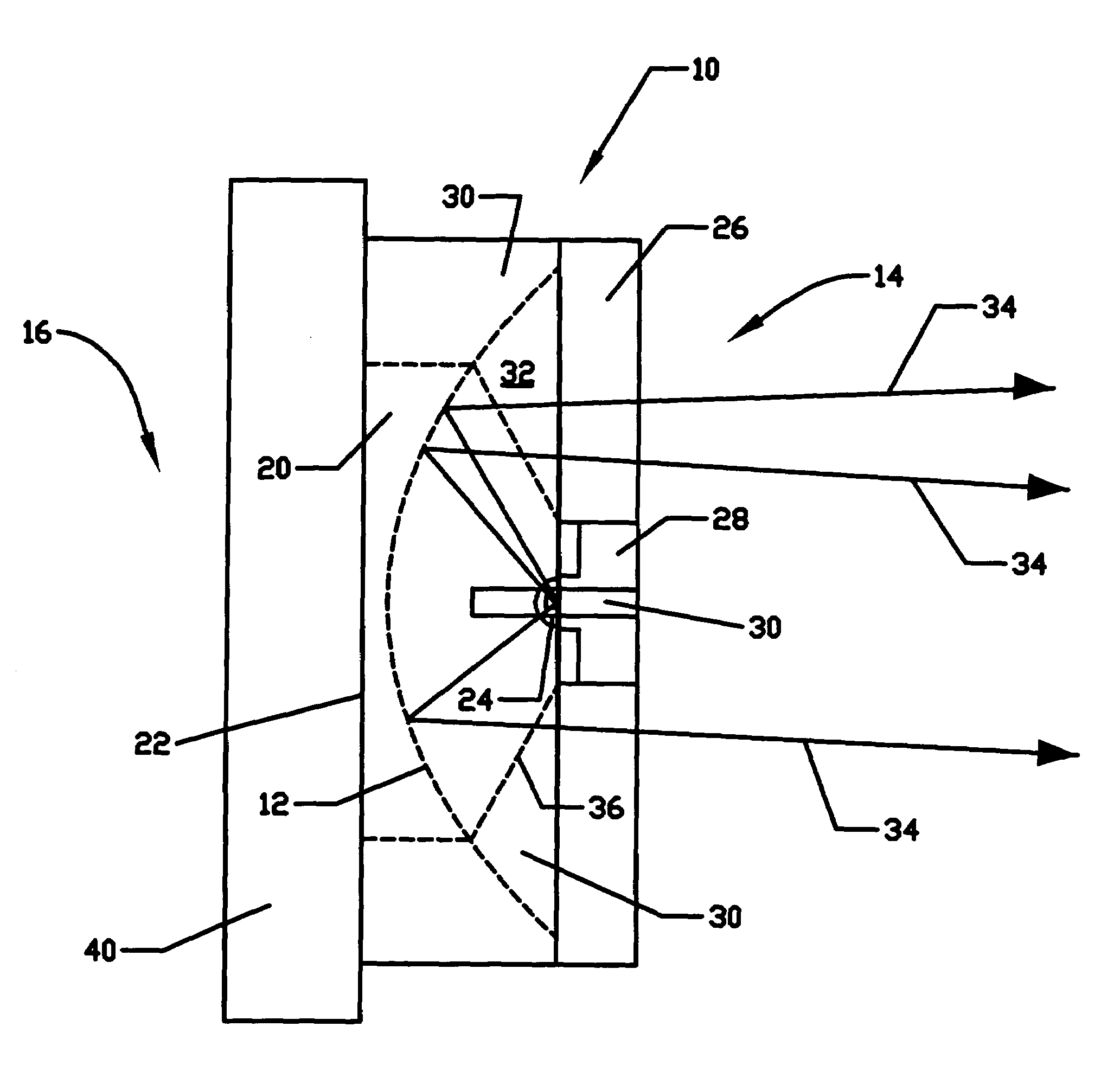
[0013]One embodiment of the invention is shown in FIGS. 4A, 4B, and 4C. The device 10 has a concave reflector 12 formed on the surface of a metallic body 20. The reflector 12 has a front side 14, a back side 16, and a central optical axis 18. The metallic body 20 acts as the heat sink, with the heat exiting the side 22 opposite the reflector 12. The LED 24 is connected to the metallic body by a “propellor” type of structure 26 with a central “hub” region 28 and one or more axial “vanes”30. The LED 24 is not seen in FIG. 4A because it is positioned on the back side of the central hub 28, facing the reflector 12. Although the vanes 30 are in the path of light 34, their large flat sides 32 do not intercept significant amounts of light 34, because the light exiting the reflector 12 is highly collimated. These large flat sides 32 are parallel to the collimated light 34, and therefore present a very small cross-section 36 to the exiting light.

[0014]FIG. 5 shows an alternate embodiment of ...


PUM


Abstract

An LED light source using back-reflecting collection optics with a supporting structure and heat sink to block only a small amount of light. A reflector has a front and back side with an LED positioned on the front side of the reflector. A heat conducting body is positioned at least partially between the reflector and the LED. The heat conducting body provides a pathway for heat to flow from the LED toward the back side of the reflector.

Description

CROSS-REFERENCE TO RELATED PATENT APPLICATIONS[0001]This application is an application claiming the benefit under 35 USC 119(e) U.S. Application 60 / 541,422, filed Feb. 3, 2004, incorporated herein by reference in its entirety.BACKGROUND OF THE INVENTION[0002]Light-emitting diodes (LEDs) are a commonly used light source in applications including lighting, signaling, signage, and displays. LEDs have several advantages over incandescent and fluorescent lamps, including high reliability, long lifetime, and high efficiency.[0003]A typical prior art LED system is shown in FIG. 1. An LED is placed on a circuit board, which carries electrical current to and from the LED, and allows heat generated by the LED to flow from the relatively small LED to a larger area, from which the heat then escapes to air. Often a heat sink is added to facilitate the heat flow to air. Light is emitted by the LED in a generally upward direction, with a wide (typically ±60–90°) angle. Many applications, such as f...

Claims


Application Information

Patent Timeline
Patent Type & Authority Patents(United States)
IPC IPC(8): F21V29/00F21V7/00F21K99/00G06M7/00H01J40/14H01L33/60H01L33/64
CPCF21K9/00F21V7/0008F21V29/004H01L33/642F21V29/006F21V29/77F21V29/89H01L33/60F21V11/06F21Y2101/02F21V19/0015H01L33/648F21Y2115/10F21K9/68F21V29/70
Inventor JACOBSON, BENJAMIN A.GENGELBACH, ROBERT D.
Owner IDEAL IND LIGHTING LLC
Why Eureka
Try Eureka