Pipe racking system

a pipe racking and pipe technology, applied in the direction of drilling rods, lifting devices, drilling pipes, etc., can solve the problems of slow pipe moving method and can be rather dangerous for the derrick man, and achieve the effect of safe and efficient pipe movement, and reducing the risk of injury

Active Publication Date: 2007-07-24
NAT OILWELL DHT
View PDF9 Cites 64 Cited by
  • Summary
  • Abstract
  • Description
  • Claims
  • Application Information

AI Technical Summary

Benefits of technology

[0008]The invention of the present disclosure is directed to a pipe racking system that enables the safe and efficient movement of pipe between a well center and a storage rack. Together with the use of its mechanized fingerboard, the system mechanizes the process of handling and storing drill pipe and / or drill collars vertically, thus eliminating the need for a worker at the racking board level. This results in reduced risk of injury and much safer practices for pipe handling. While adaptable for various operating environments, the pipe racking system is particularly well suited for land-based drilling rigs.
[0012]1. Capable of remaining installed in the mast during rig moves thus minimizing any disassembly for rig-down;
[0017]6. Compliments and enhances the efficiency of other automated drilling systems such as the Iron Roughneck, Top Drive, and Power Slips.

Problems solved by technology

This method of moving pipe can be slow and also can be rather dangerous for the derrick man.

Method used


Image

  • Pipe racking system
  • Pipe racking system
  • Pipe racking system

Examples


Embodiment Construction

[0034]Illustrative embodiments of the invention are described below as they might be employed in the use of designs for a pipe racking system. In the interest of clarity, not all features of an actual implementation are described in this specification. It will of course be appreciated that in the development of any such actual embodiment, numerous implementation-specific decisions must be made to achieve the developers' specific goals, such as compliance with system-related and business-related constraints, which will vary from one implementation to another. Moreover, it will be appreciated that such a development effort might be complex and time-consuming, but would nevertheless be a routine undertaking for those of ordinary skill in the art having the benefit of this disclosure.

[0035]Further aspects and advantages of the various embodiments of the invention will become apparent from consideration of the following description and drawings.

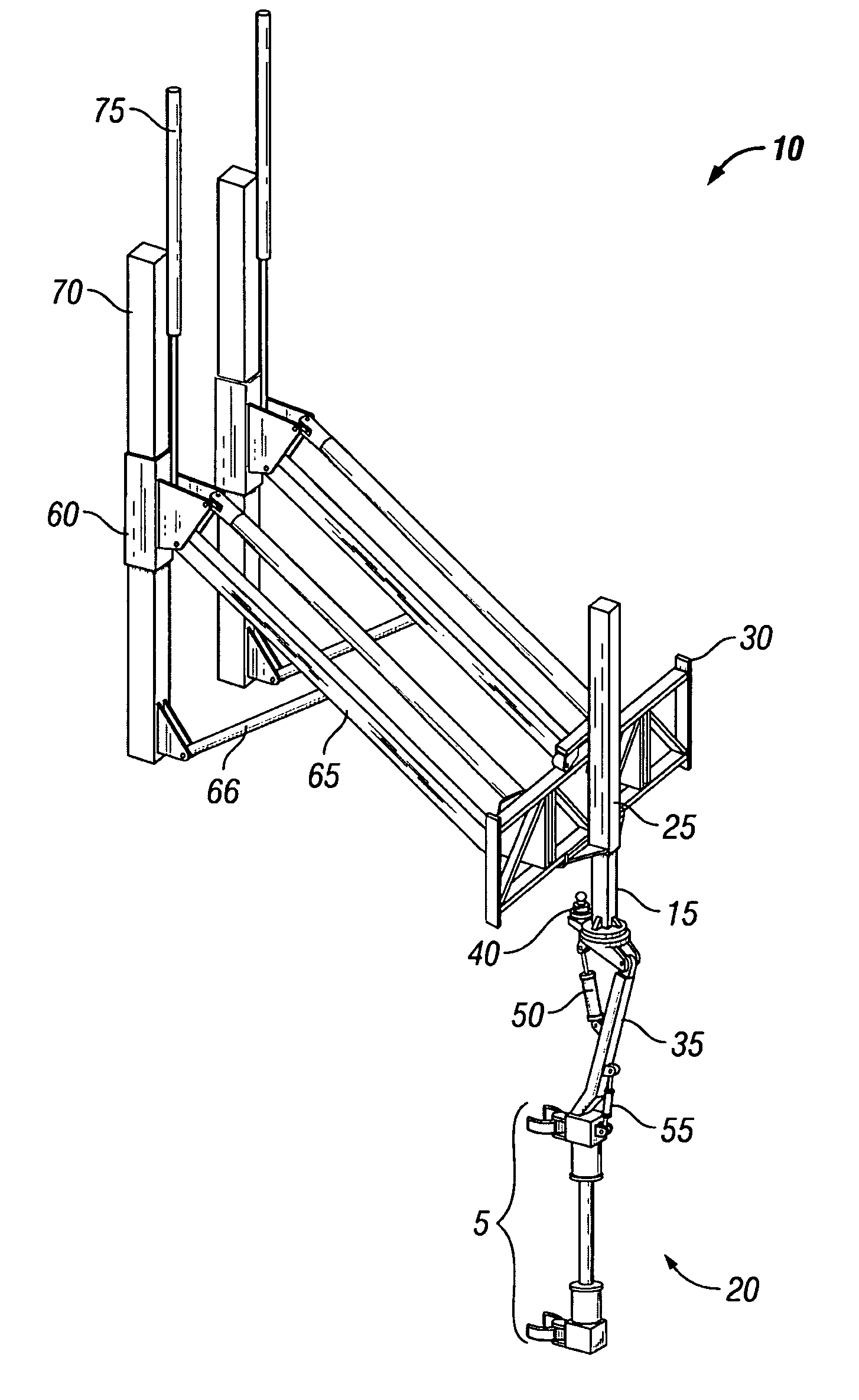
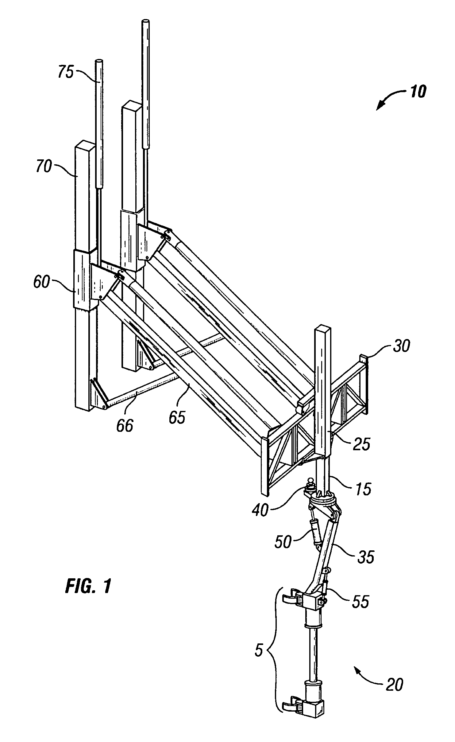
[0036]FIG. 1 shows a pipe racking system 10...


PUM


Abstract

The pipe racking system is designed to handle drilling tubulars (primarily drill pipe and drill collars) between the racked or setback position and the well center. The racking system can mechanically grasp a stand of pipe, lift the pipe sufficient for free movement, and deliver the pipe to either the setback area for storage or to well center to be added to the drilling string. The purpose of this newly developed system is to move pipe safely and efficiently in the vertical position for drilling operations. Together with the use of its mechanized fingerboard, the system automates the process of handling and storing pipe vertically, thus eliminating the need for a worker at the racking board level. The system is capable of being installed within the masts of smaller rigs and may remain installed in the mast during rig moves thus minimizing any disassembly for rig-down.

Description

CROSS REFERENCE TO RELATED APPLICATION[0001]This application is a non-provisional utility application claiming priority to U.S. Provisional patent application No. 60 / 612,026, entitled, “Pipe Racking System,” by Tom Bui, Mark J. Fillip, Ryllee Tab Tettleton, and Baldwin Zahn, filed Sep. 22, 2004, incorporated by reference herein in its entirety.BACKGROUND OF THE INVENTION[0002]1. Field of the Invention[0003]The present invention is directed to a pipe racking system for use on a drilling rig. More particularly, the system is designed to move pipe safely and efficiently in the vertical, or near vertical, position for drilling operations.[0004]2. Description of the Related Art[0005]In rotary drilling, a pipe string is positioned into a hole or well and then rotated to drill down into the earth. As the depth of the well increases, the pipe string needs to be lengthened. The pipe string is lengthened by the addition of a section of pipe to the surface end. In order to reach the depths whe...

Claims


Application Information

Patent Timeline
Patent Type & Authority Patents(United States)
IPC IPC(8): E21B19/00A01G23/02
CPCE21B19/14
Inventor ZAHN, BALDWIN E.FILLIP, MARK J.TETTLETON, RYLLEE TABBUI, TOM
Owner NAT OILWELL DHT
Why Eureka
Try Eureka