System for handling riser pipe

a technology of riser pipe and moving system, which is applied in the direction of pipe-laying vessels, earth-moving drilling and mining, drilling accessories, etc., can solve the problems of reducing the performance of the crew, exposing the operators themselves to conditions of possible danger, and poor automation of the process, so as to reduce the number of transfer of tubular elements or risers between different types of machines, the effect of reducing the number of transfers

Active Publication Date: 2016-06-16
NAVALIMPIANTI +1
View PDF12 Cites 0 Cited by
  • Summary
  • Abstract
  • Description
  • Claims
  • Application Information

AI Technical Summary

Benefits of technology

[0031]The solution according to the present invention, by the considerable creative contribution the effect of which constitutes an immediate and important technical progress, presents various advantages.
[0032]Advantageously, the solution according to the present invention allows to best use the space available inside the hold where the tubular elements are stored obtaining definitely more favourable coefficients of filling of the hold with respect to the prior art solutions. In this way it is possible either to load a greater number of tubular elements onto the same vessel or to design smaller-sized vessels with an equal number of tubular elements that one can load, with consequent economic benefits both in the phase of construction of the vessel and during the operation of the latter.
[0033]In general the solution according to the present invention allows to eliminate the traditional lifting members, normally made up of bridge cranes, hold elevators and deck cranes, replacing them with more effective and safer devices able to ensure the movement of the tubular elements or risers in conditions of maximum safety. Furthermore, it allows for a high degree of automation of the process of movement of the tubular elements. Moreover, the number of transfers of the tubular elements or risers between different types of machines is minimized.
[0034]With reference to the movement device of the invention that realizes the movement of the tubular elements or risers within the hold of a vessel, the solution according to the present invention allows to solve the safety problems related to the presence of suspended loads because the solution according to the present invention allows to obtain a movement of the tubular elements in a locking condition on the driving means, eliminating all the conditions of presence of suspended loads. This is further advantageous because impacts are prevented, which may damage the tubular elements. Further advantageously the solution according to the present invention also allows to completely automate the transfer phase as well as the hold loading phase, so that the operators no longer have to handle the driving means manually, reducing the possibilities of error and reducing the exposure of the operators to conditions of danger. Furthermore, the solution according to the present invention also allows to maintain high standards of operative efficiency also in the case of changes of the crew or of the operators. Furthermore, the solution according to the present invention facilitates the phases of inspection of the tubular elements prior to their taking out from the storage stacks and also allows to know with precision and automatically the position of the various types of tubular elements or risers present in the storage stacks. Moreover, the solution according to the present invention allows for the assembly of the movement devices for tubular elements also on existing ships and, anyway, after the launch of the ship itself, preventing the movement devices from remaining exposed to the weather for long periods of time.
[0035]With reference to the lifting device of the invention that realizes the movement of the tubular elements or risers in correspondence with the deck of the vessel, the solution according to the present invention allows to carry out the movement of the tubular elements or risers on the deck without having to use the on-board cranes and, therefore, completely eliminating the suspended loads, to the advantage of the personnel's safety and of the preservation of the riser from possible damage. This is further advantageous as impacts are prevented, which may damage the tubular elements. Furthermore it advantageously allows for an efficient transfer of the tubular elements or risers between the taking out position within the hold or on the deck and the unload position towards the transfer device with one single operation in a constant condition of locking of the tubular element or riser.
[0036]Advantageously the solution according to the present invention allows to obtain a movement system for tubular elements that is able to manage in an automatic way the entire movement of the tubular elements themselves both in the loading phase of the tubular elements within the storage zone and during the laying phase of the tubular elements. The system according to the present invention also allows to have one single subject supplying the entire management and movement chain of the tubular elements, to the advantage of the reciprocal integration of the various constituents of the system and to the advantage of an efficient and safe movement of the tubular elements themselves.

Problems solved by technology

First of all in the prior art solutions in which the tubular elements or risers are stored in a covered hold and the movement of the tubular elements occurs by means of bridge cranes there are both safety problems concerning the movement of loads suspended over a vessel and efficiency problems in the exploitation of the space available in the hold of the vessel. In fact, the bridge crane arranged inside the hold occupies a great space for the entire length of the hold itself and this space, intended for the movement of the bridge crane over the stacks of tubular elements, is actually unused space for storage.
Furthermore, the movement of the tubular elements, which are very heavy, by means of bridge cranes and with suspension cables or rigid elements, exposes the tubular elements to impacts that may compromise their tightness or coupling.
Moreover, the presence of the operators in the control zones exposes the operators themselves to conditions of possible danger.
Furthermore, the poor automation of the process is often a serious problem in the phases of the operators' shift change.
In fact when, after about six months, the operators are replaced by a new crew, a reduction in the crew's performance occurs with a consequent slowdown in the operations of laying of the tubular elements.
Furthermore, the prior art solutions make the phases of inspection of the tubular elements prior to their taking out difficult.
Before the hold is definitively closed the bridge crane remains exposed to the weather and damage that may compromise its functionality before the launch of the ship.
At present the selection of the risers to be taken as well as their loading operations are carried out by the operators manually, exposing the procedure to errors that may have serious consequences from the environmental point of view or, in any case, slowdowns in the operations of taking out or loading of the risers.
Further drawbacks of the prior art solutions derive from the fact that all the devices involved in the movement of the tubular elements are often considered separately starting from the ship design phase, but also in the phase of fitting out of the ship and even in the phase of use of the devices themselves.
The movement activities of the tubular elements, particularly in the case of the risers, are often made complex due to the number of necessary operations and to the number of various machines involved, which are not coordinated or integrated with one another and which must be necessarily managed manually by single operators with all the risks connected to errors of movement, fall of suspended loads, impacts, damage, etc.
As a consequence, a drawback of the prior art systems is that the loading and the taking out of the risers generally occurs manually by the operators who establish the order of loading.
An error by those who are in charge of the loading may cause following delays in the laying phase for example in the case in which a riser suitable to operate at great depths (that must be taken before the others) has been loaded on a bottom rack and below with respect to a series of risers suitable to operate at shallow depths (that must be the last to be taken).
Furthermore, if the operators in charge of the laying do not notice the error, they might lay at great depths a riser that is not suitable to operate at such depths with the risk of breaks that may cause irreparable environmental damage and compromise the operators' safety.

Method used


Image

  • System for handling riser pipe
  • System for handling riser pipe
  • System for handling riser pipe

Examples


Embodiment Construction

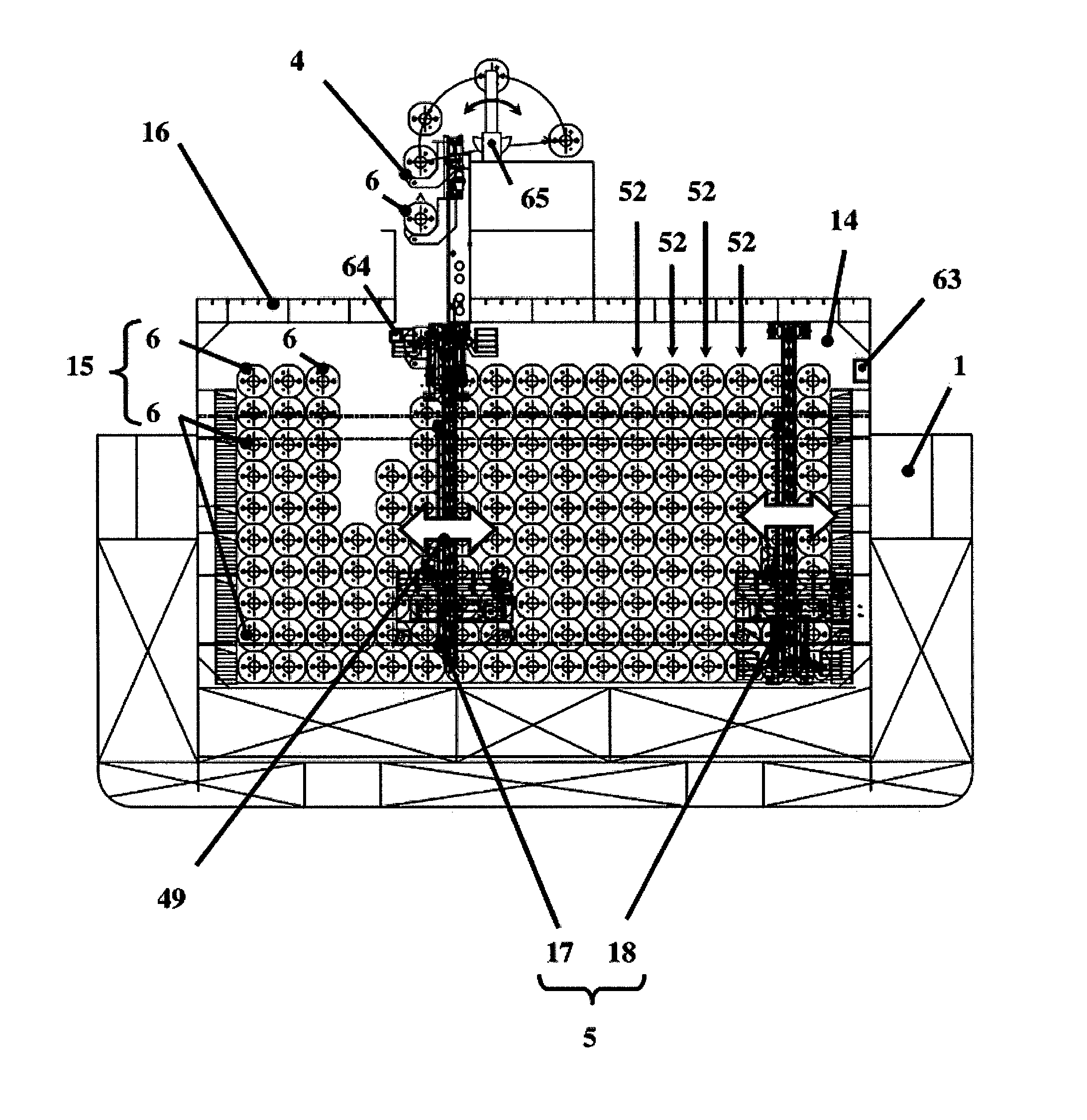
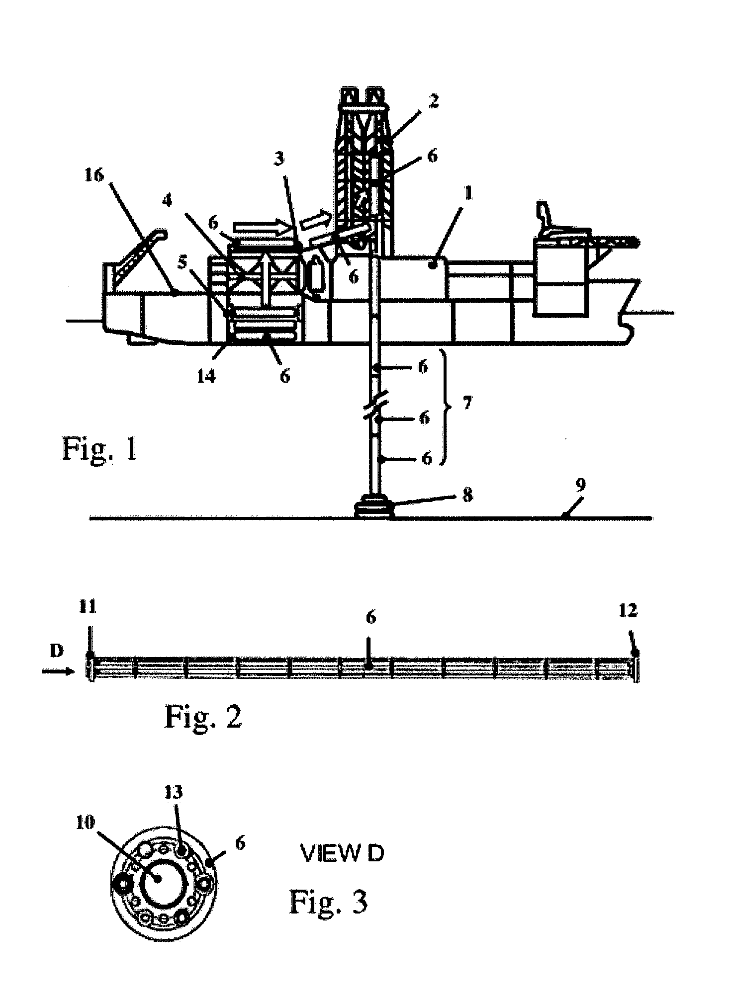
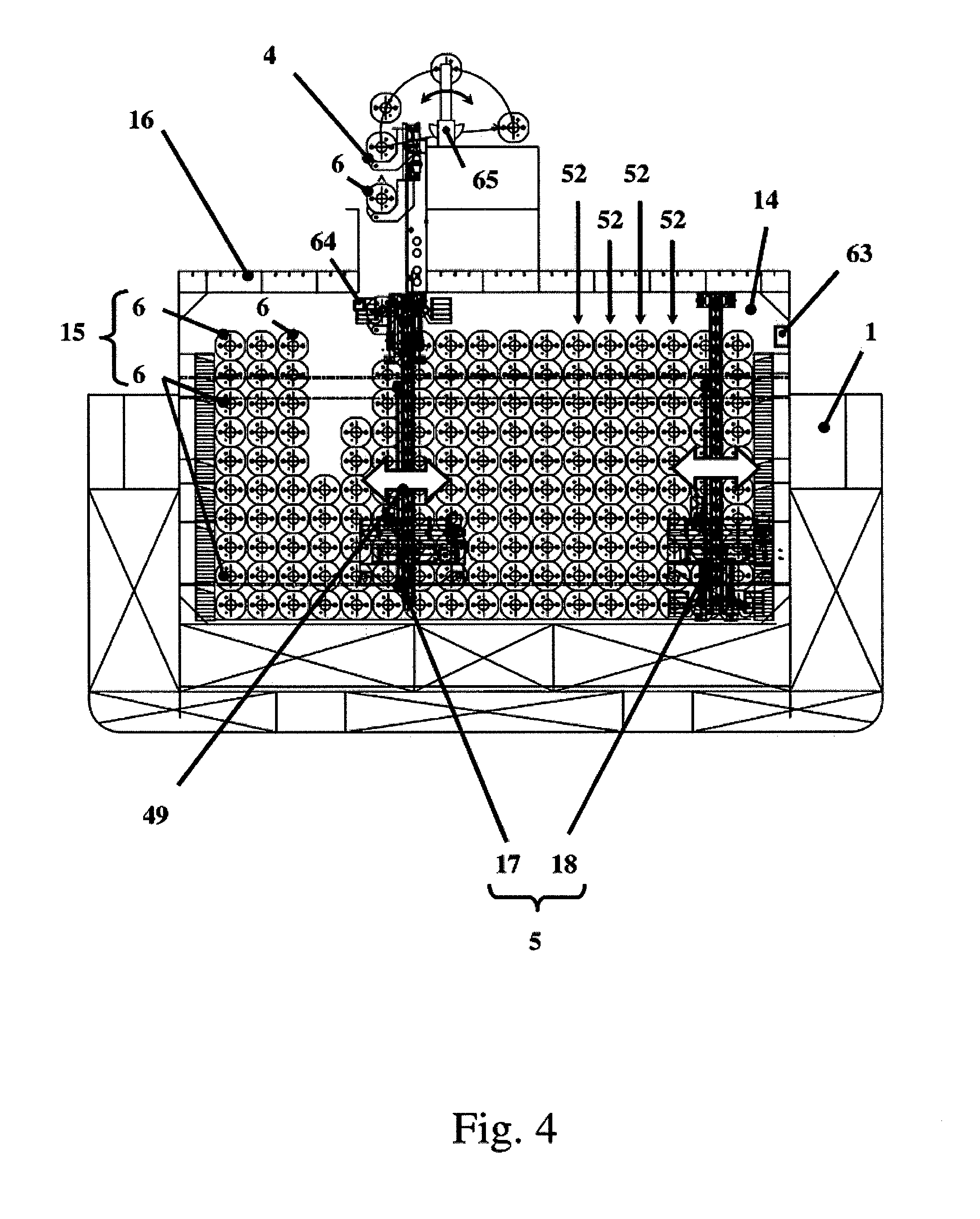
[0081]With reference to the figures (FIG. 1) the present invention finds application in the movement of tubular elements (6) from a storage zone (14) of a vessel (1) towards at least one laying or use zone (2) of the tubular elements. For example, without limitation for the purpose of the present invention, in the case of a drillship or in the case of a semisubmersible drilling rig, the tubular elements will be risers that are taken from a storage zone (14) that can be a hold or a deposition zone on the deck. The risers (6) are (FIG. 2, FIG. 3) normally tubular elements flanged in correspondence with a first end (11) and in correspondence with a second end (12) that are opposite ends with respect to the longitudinal development of the tubular element in the form of a riser. The riser (FIG. 3) includes a main hole (10) and a number of auxiliary lines (13) for the passage of the control fluids, as well as floating pushing elements inserted around the structure of the riser itself. Onc...


PUM


Abstract

System for handling riser pipe on an offshore vessel comprising a lifting device for lifting the pipe from a storage zone onto the deck.

Description

TECHNICAL FIELD[0001]The present invention relates to a movement system for tubular elements on a vessel according to the characteristics of the pre-characterizing part of claim 1.[0002]The present invention also relates to vessels according to the characteristics of claims 36 to 38.DEFINITIONS[0003]In the present description and in the appended claims the following terms must be understood according to the definitions given in the following.[0004]In the present description and in the appended claims by the general expression “vessels” one will indicate ships, boats, rigs, floating structures in general and in particular drillships, semisubmersible drilling rigs.[0005]In the present description and in the appended claims by the general expression “tubular elements” one will indicate both real pipes suitable to be laid on the sea or ocean bed by means of pipe-laying vessels, or the so-called “risers” which are tubular elements suitable to be reciprocally fastened after one another to...

Claims


Application Information

Patent Timeline
Patent Type & Authority Applications(United States)
IPC IPC(8): E21B19/14B63B35/03E21B17/01
CPCE21B19/143B63B35/03E21B17/01
Inventor MISSION, ANGELOAMBROSIO, LUCA
Owner NAVALIMPIANTI
Why Eureka
Try Eureka