Multi-element blade with aerodynamic profiles

a multi-element blade and aerodynamic technology, applied in wind turbines, machines/engines, wind energy generation, etc., can solve the problems of high cost of transportation of blades, blades with greater dimensions already exceeding this limit, and reducing the dimensions of blades, facilitating logistic procedures, and increasing the aerodynamic efficiency of blades

Inactive Publication Date: 2009-03-26
TECSIS TECHNOLOGIA E SISTEMAS AVANCADOS
View PDF8 Cites 17 Cited by
  • Summary
  • Abstract
  • Description
  • Claims
  • Application Information

AI Technical Summary

Benefits of technology

[0026]The use of a blade divided into two or more elements allows the primary element, which is larger, to be made up of a profile with a relatively small chord. This way, the assembly of multi-element blades can be transported, handled and stored separating the complementary aerodynamic profiles, which reduces the dimensions of said blade and greatly facilitates the logistic procedures. It is also possible to transport the complementary elements, for example, in the same truck transporting the primary element, placing the primary complementary element collaterally to the primary element, however with the root of the first complementary element near the edge of the primary element. The other complementary elements can also be arranged similarly, each one in the opposite direction to the former.
[0027]The use of two or more collateral aerodynamic profiles in the region of the larger chord also has the additional effect of increasing the blade's aerodynamic efficiency. The best performance is provided by the aerodynamic interference generated between the profile elements, to the extent that the joint action of the elements increases the maximum lift coefficient and the angles of attack without causing early stall. In addition, the arrangement of profiles concentrated in the region of the blade root generates greater lift coefficient in this region, where the tangential speed is low, thus guaranteeing better energy use of weak winds (cut in) in this part as well.
[0028]In addition, as a fastening system, it is easy to install in the field, allowing quick assembly and installation in the wind energy plant, since it preferably has no pivotable parts. Furthermore, the fastening system itself can constitute a profile with complementary aerodynamic profile, eliminating vortices from the edge of the elements.

Problems solved by technology

These improvements, however, cause several difficulties in the logistic processes, among which are particularly highlighted the handling, storage and transportation of the structures, by land, sea or air.
This way, these blades have high cost of transport due to the singular geometry, with great longitudinal and transversal dimensions, requiring special cares to prevent damages during the logistic procedures.
Today, blades with greater dimensions already exceed this limit and suffer many restrictions to reach the installation site of the wind turbine.
Furthermore, the larger the blades the greater the problems to use standard handling equipment such as hoists; as well as standard storage and transport packages.
On the other hand, when changes are made in the blades only in function of problems in the logistic procedures, without concern with issues of performance and aerodynamic control, there is a great loss in the capacity and versatility of the power generation of wind turbines.
Few solutions, however, are concerned with both factors at the same time.

Method used


Image

  • Multi-element blade with aerodynamic profiles
  • Multi-element blade with aerodynamic profiles
  • Multi-element blade with aerodynamic profiles

Examples


Embodiment Construction

[0041]The various modes of execution of this invention are not limited to the constructive details explained in this description and figures, to the extent that this invention can be realized by other equivalent configurations.

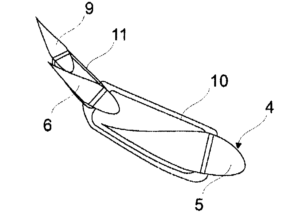
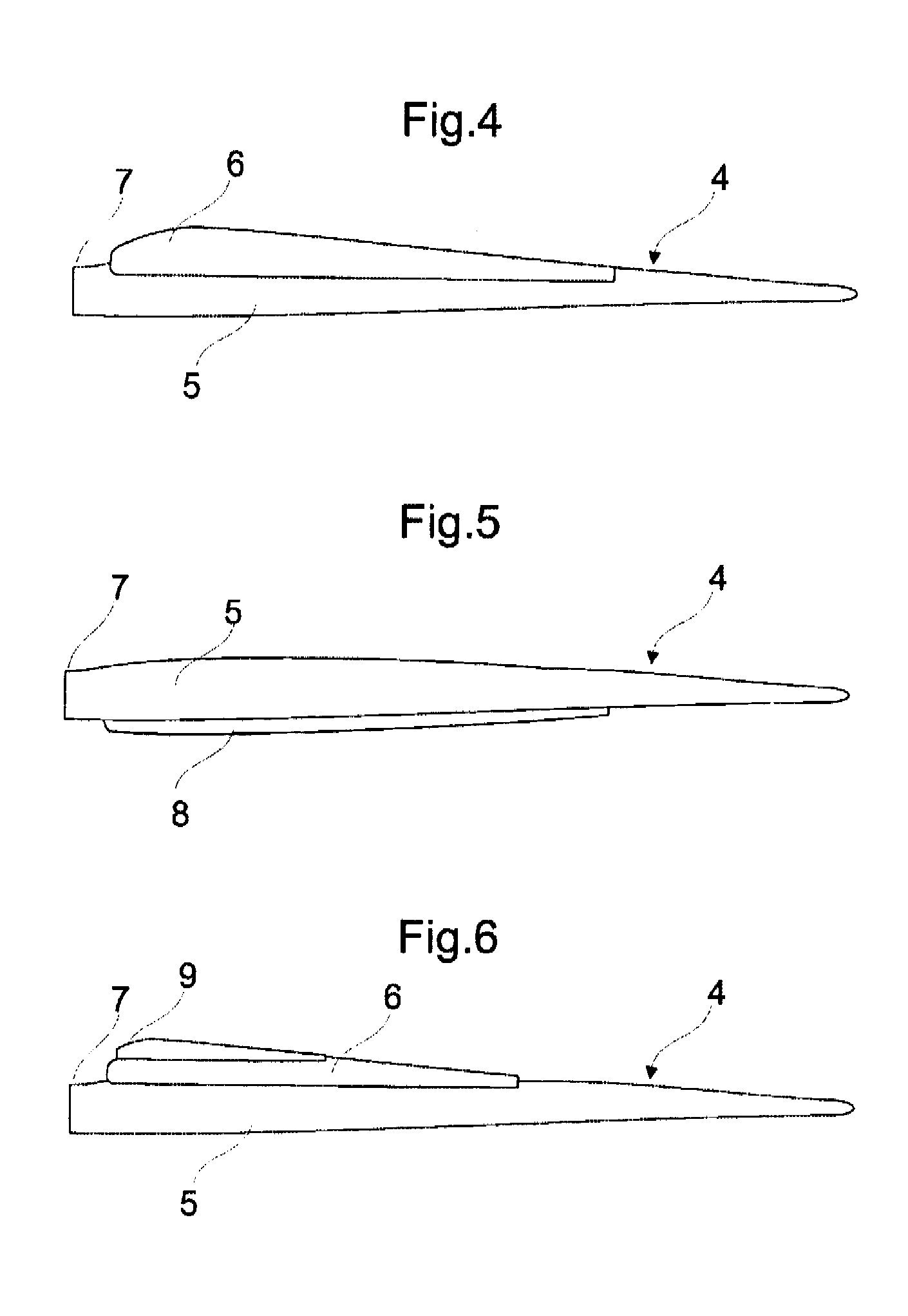
[0042]This invention, therefore, basically consists in a blade applied in horizontal rotation wind turbine rotors, with blades perpendicular to the axis of rotation, in which each one of said blades is made up of various elements forming aerodynamic profiles fixed between them by means of fastening elements, being that the elements forming profiles are positioned in the region closer to the blade root.

[0043]FIG. 1 shows a longitudinal plane view of a conventional blade (1). As can be seen in this figure, the chord in the root is relatively greater than at the edge of the blade, being that in a certain straight section there is a maximum chord (Cmax). Different geometries, sizes, internal structures and raw materials can be used to obtain a specific blade for a...


PUM


Abstract

The objective of this invention is to obtain rotor blades for large-sized horizontal axis wind turbines that allow easy transport, handling and storage at the same time guaranteeing greater efficiency in the use of wind energy. The present invention results in a blade (4) made up of two or more elements (5,6,9) arranged collaterally and preferably fixed among themselves such as to cause an aerodynamic interference between said elements.

Description

TECHNICAL FIELD[0001]This invention refers to the technical field of mechanisms to convert kinetic energy of natural wind into useful mechanical power with the aim of generating electric power, more particularly the constructive arrangements applied on wind turbine rotors blades.BACKGROUND ART[0002]Electricity production by means of wind energy is among renewable energy sources that had the most development in recent years. This growth is due to this source's attractive characteristics, mainly when the ecological benefits are considered, such as the low environmental impact, non-emission of gases, radioactive particles or residues. Furthermore, arrangements adopted in wind energy plants allow rapid addition of extra modules in cases of increase in energy demand. In addition, since the base of the support structures for the wind turbines occupies reduced area, the adjacent areas can be used for other purposes, like agriculture.[0003]Said wind turbines are basically made up of a suppo...

Claims


Application Information

Patent Timeline
Patent Type & Authority Applications(United States)
IPC IPC(8): F03D1/06
CPCY02E10/721F03D1/0675Y02E10/72
Inventor KOIKE, BENTO MASSAHIKO
Owner TECSIS TECHNOLOGIA E SISTEMAS AVANCADOS
Why Eureka
Try Eureka