Melting plate candles

a technology of melting plate and candles, which is applied in the direction of burners, combustion regulation, combustion types, etc., can solve the problems of more more rapid dispensing of volatile materials, and achieve the effects of rapid temperature rise, rapid dispensing of volatile materials, and rapid melting of fuel elements

Inactive Publication Date: 2007-07-24
SC JOHNSON & SON INC
View PDF413 Cites 45 Cited by
  • Summary
  • Abstract
  • Description
  • Claims
  • Application Information

AI Technical Summary

Benefits of technology

[0016]A key element of the present invention constitutes the capillary lobe on the melting plate, which lobe provides a locating device for a complementarily shaped wick holder, creates a site for capillary feed of fuel to the wick, and provides a means for heat transfer from the flame to both the melting plate and the solid fuel. The wick holder, in addition to providing a mounting means for the wick, has a base which conforms to the capillary lobe in such a manner as to create a capillary feed by which melted wax flows to the wick as fuel. In addition to the base or skirt of the wick holder being a heat conductive element, the wick holder may also provide an additional heat conductive element such as a fin, which may be in close proximity to, or in contact with the flame, and thereby conduct heat back to the wick holder base, and thus the capillary lobe, and thereby to both the melting plate and the fuel. It is to be understood that this arrangement of elements provides for much greater control of the degree of...

Problems solved by technology

Such a rapid temperature rise clearly results in a more rapid mel...

Method used


Image

  • Melting plate candles
  • Melting plate candles
  • Melting plate candles

Examples


Embodiment Construction

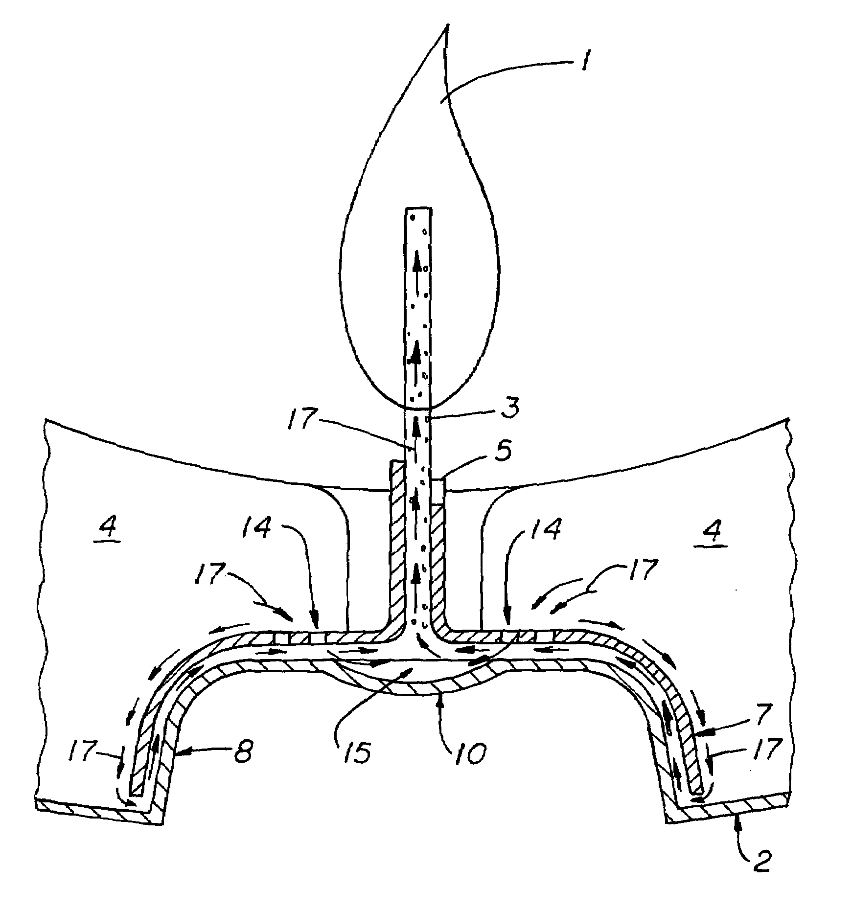
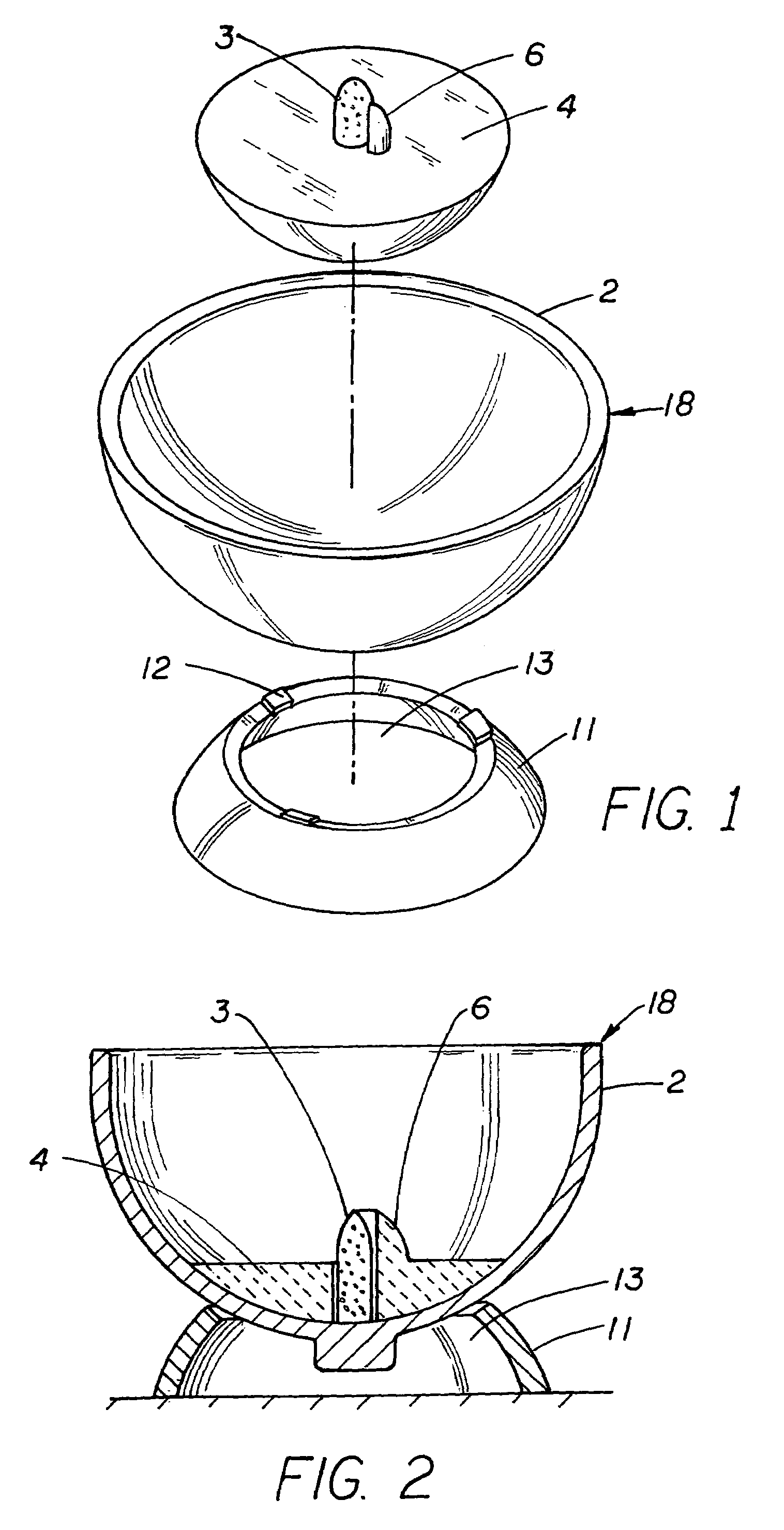
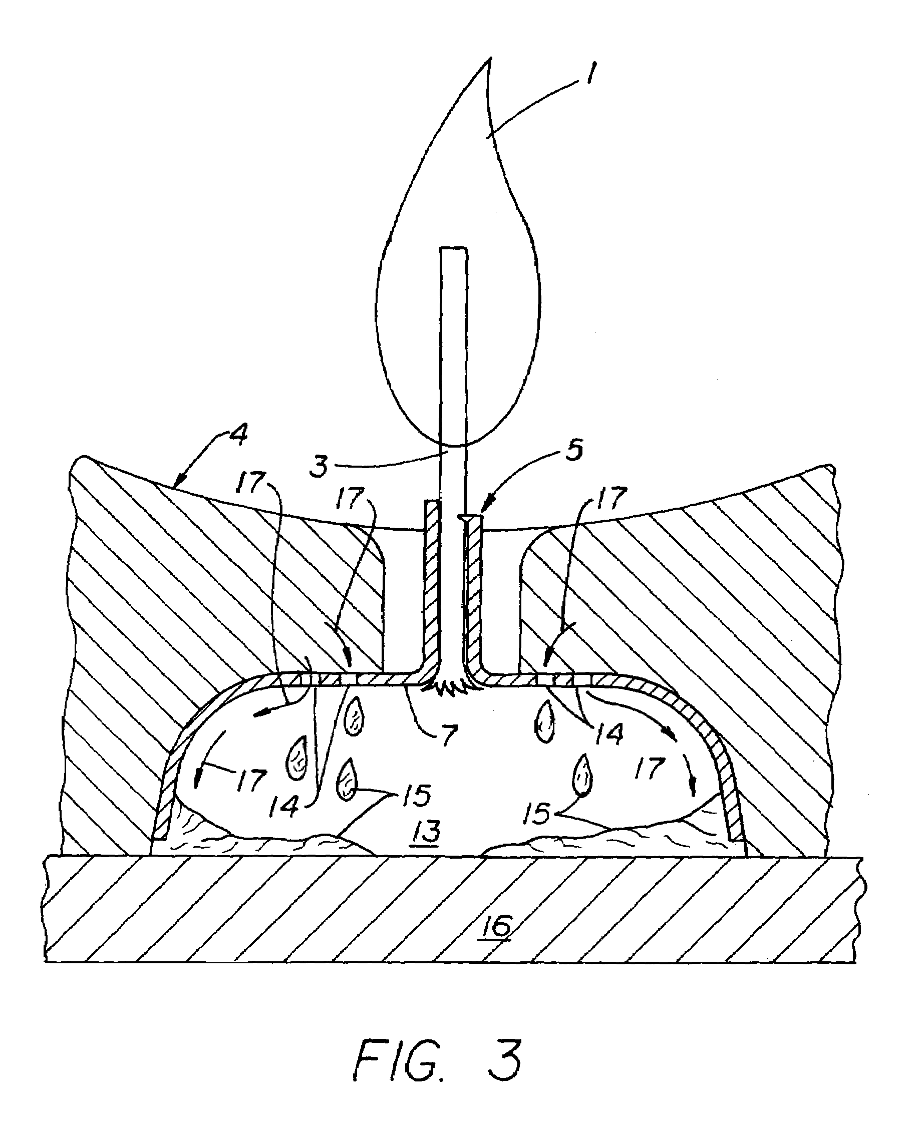
[0026]The present invention provides a means for the burning of solid fuel elements, wherein said means ensure the maximum utilization of the solid fuel provided. The melting plate devices of the present invention comprise a container for solid or gel fuels, and a wick holder comprising a wick and optional heat transfer elements. These devices provide an improved transfer of heat from a heat source, i.e. a flame burning the fuel at the wick, to the remaining fuel and, more importantly, back to the container holding said fuel. Such devices are preferably both functional and designed so as to be decorative or esthetically pleasing.

[0027]The melting plate candle of the present invention comprises a fuel element, and a container encompassing the fuel, said container comprising a heat conductive support plate, or melting plate, in direct contact and in supporting or containing relationship, with the fuel element. The melting plate candle of the present invention may further comprise addi...


PUM


Abstract

The present invention relates to melting plate candles which employ heat conductive elements to distribute heat from a burning flame at a wick to a support plate for a solid fuel and to the body of said solid fuel, so as to more rapidly liquify the solid fuel, such as paraffin wax, and to more uniformly and intensely heat such fuels to increase the efficiency of consumption thereof and to more rapidly release volatile materials contained within said fuels. The heat conductive support plate is configured so as to have a capillary lobe upon the surface thereof, which cooperatively engages a wick holder comprising a preferably consumable wick and heat conductive fins which conduct heat from a flame upon said wick to said support plate, said wick holder further engaging said solid fuel, and said support plate being configured so as to cause the flow of liquified fuel to the wick holder. The fuel may be provided in various forms, configured to cooperatively engage said wick holder and support plate, and may comprise various volatile materials. The capillary lobe, in conjunction with the wick holder, causes rapid and complete flow of the liquefied fuel to said wick.

Description

RELATED APPLICATION[0001]This is a Continuation-In-Part application of Ser. No. 09 / 747,525, filed Dec. 20, 2000, now U.S. Pat. No. 6,802,707, which is in turn a Continuation-in-Part application of Ser. No. 09 / 468,970, filed Dec. 21, 1999, since abandoned.FEDERALLY SPONSORED RESEARCH OR DEVELOPMENT[0002]Not Applicable.BACKGROUND OF THE INVENTION[0003]The present invention relates to means to provide an improved fuel burning element, such as a candle or lamp, which consumes fuel more efficiently while presenting an improved means for distribution of volatile materials, while also providing an improved degree of safety while burning, and a candle holder which requires little or no cleaning to remove wax residue. The candles or lamps of the present invention comprise a solid fuel element located on a melting plate, a preferably consumable wick, and heat conductive means in the wick holder to transfer heat from the burning fuel, i.e. the flame, to the remaining fuel, thereby assuring its...

Claims


Application Information

Patent Timeline
IPC IPC(8): F23D3/16F21V37/00
CPCF21V37/00F23D3/16F23D3/24
Inventor FURNER, PAUL E.
Owner SC JOHNSON & SON INC
Why Eureka
Try Eureka