Elbow prosthesis

a technology for elbows and prostheses, applied in the field of elbow prostheses, can solve the problems of elbow prosthesis assembly, significant cost, and difficulty in later methods, and achieve the effect of reducing the difficulty of later methods and reducing the cost of the elbow prosthesis

Inactive Publication Date: 2007-07-24
ENCORE MEDICAL L P D B A DJO SURGICAL
View PDF44 Cites 60 Cited by
  • Summary
  • Abstract
  • Description
  • Claims
  • Application Information

AI Technical Summary

Benefits of technology

[0008]It is a general object of the present invention to provide a prosthetic joint kit which transmits load through mating bearing components over a spherically shaped area so as to minimize stresses in the bearing components, more accurately mimic normal joint motion and provide for ease of assembly and revision.

Problems solved by technology

One significant drawback concerns the assembly of the elbow prosthesis after the surgeon has cemented the humeral and ulna stems to their respective bones.
As a high degree of accuracy is typically required to ensure proper alignment between the hole in the humerus and the hole in the yoke of the humeral stem, a significant cost can be associated with this step in the installation of an elbow prosthesis due to the cost of the tooling used and the amount of time required to complete this step.
This later method is typically somewhat difficult, given the limited amount of joint space that is available and the time constraints associated with the use of a PMMA bone cement.
For instance, a retaining pin that is transverse to the longitudinal axis of the patient is employed, thereby making its removal difficult if a bearing need to be replaced.

Method used


Image

  • Elbow prosthesis
  • Elbow prosthesis
  • Elbow prosthesis

Examples


Embodiment Construction

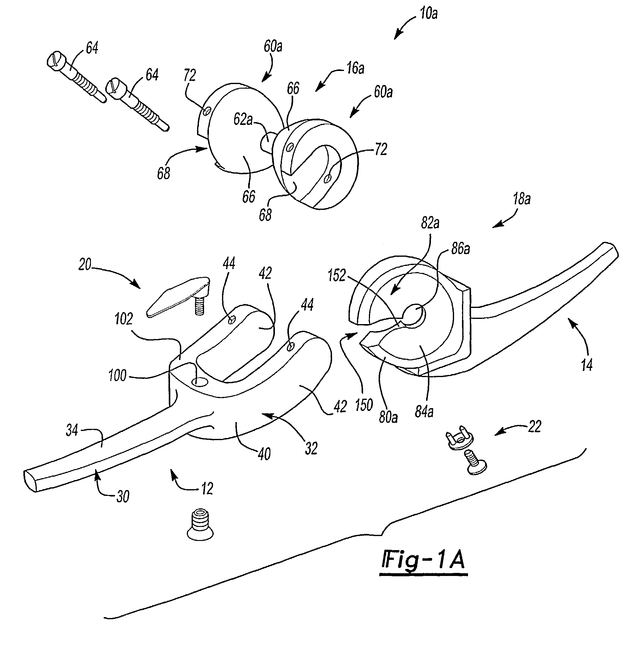
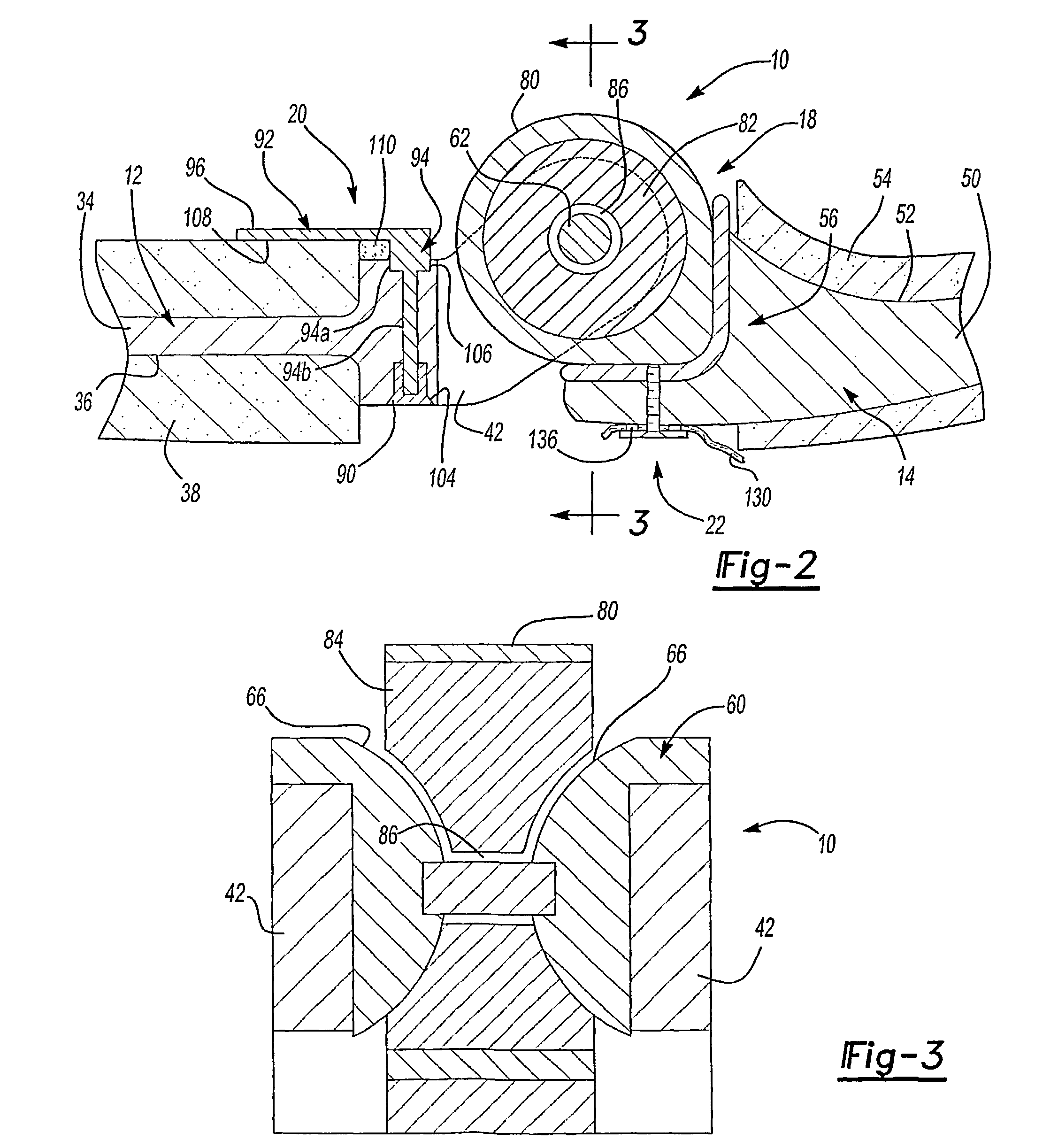
[0057]With reference to FIGS. 1, 2 and 3 of the drawings, a linked prosthetic joint device constructed in accordance with the teachings of a first aspect of the present invention is generally indicated by reference number 10. Although the particular prosthesis illustrated and discussed relates to a prosthesis for use in reconstructing an elbow, it will be understood that the teachings of the present invention have applicability to other types of linked and unlinked prosthetic devices. As such, the scope of the present invention will not be limited to applications involving elbow prosthesis but will extend to other prosthetic applications.

[0058]In the particular embodiment illustrated, linked prosthetic joint 10 is shown to include a first stem structure 12, a second stem structure 14, a first bearing component 16, a second bearing component 18, a modular flange 20 and a tissue fastener 22. First stem structure 12 includes a proximal portion 30 and a distal portion 32. Proximal porti...


PUM


Abstract

A prosthetic joint kit that is particularly well suited for an elbow. In each of the various embodiments, the prosthetic joint kit transmits load through the prosthetic joint through a pair of spherically shaped bearing surfaces so as to transmit load over a relatively large area rather than at a point or over a line of contact. The prosthetic joint kit may be configured in a modular manner wherein a plurality of interchangeable stem structures, being structures and / or bearing inserts of various types are available. Construction in this manner enables a surgeon to configure the prosthetic joint to best suit the needs of the patient. For example, the surgeon may employ a modular flange for compressing a bone graft, a tissue fastener for securing soft tissue to a portion of the prosthetic joint, a cam for limiting the amount by which the prosthetic joint articulates or a bearing insert for tailoring the degree of varus / valgus constraint.

Description

CROSS-REFERENCE TO RELATED APPLICATIONS[0001]This application claims the benefit of U.S. Provisional Application No. 60 / 219,103 filed Jul. 18, 2000.TECHNICAL FIELD[0002]The present invention relates generally to prosthetic devices used in elbow arthroplasty and more particularly to a modular elbow prosthesis.BACKGROUND OF THE INVENTIONBackground Art[0003]Linked or constrained elbow prostheses are known which comprise simple hinge arrangements, one component of which is attached to the end of the humerus and the other component of which is attached to the end of the ulna. The humeral component includes a shaft, that is cemented into a prepared cavity in the end of the humerus, and the ulnar component includes a shaft, that is cemented to the end of the ulna. The components of the prosthesis are connected together by means of a hinge pin so that the prosthesis allows a single degree of freedom of movement of the ulna relative to the humerus.[0004]One example of a linked elbow prosthes...

Claims


Application Information

Patent Timeline
Patent Type & Authority Patents(United States)
IPC IPC(8): A61F2/38A61B17/82A61F2/00A61F2/08A61F2/28A61F2/30A61F2/46
CPCA61F2/3804A61B17/82A61F2/0811A61F2/384A61F2002/2835A61F2002/30153A61F2002/30172A61F2002/30192A61F2002/30327A61F2002/30329A61F2002/30332A61F2002/30382A61F2002/30383A61F2002/30387A61F2002/30388A61F2002/30395A61F2002/30403A61F2002/30433A61F2002/30462A61F2002/30476A61F2002/3049A61F2002/30492A61F2002/30497A61F2002/305A61F2002/30504A61F2002/30507A61F2002/3054A61F2002/30596A61F2002/30604A61F2002/30607A61F2002/30616A61F2002/30624A61F2002/30632A61F2002/30665A61F2002/3069A61F2002/30772A61F2002/30774A61F2002/30785A61F2002/30792A61F2002/30797A61F2002/30878A61F2002/30975A61F2002/3809A61F2002/3813A61F2002/3822A61F2002/3827A61F2002/3831A61F2002/4602A61F2220/0025A61F2220/0033A61F2220/0041A61F2220/0075A61F2230/0019A61F2230/0041A61F2230/0052A61F2250/0039A61F2250/0062A61F2310/00017A61F2310/00029A61F2310/00161A61F2310/00179A61F2/4601A61F2002/30331A61F2002/30495A61F2002/30594A61F2002/3079A61B17/86A61F2/30767A61F2/38A61F2002/30131A61F2002/30367A61F2002/30578
Inventor GRAHAM, THOMAS JBERELSMAN, BRIAN KHASTINGS, HILLSTONE, KEVIN T
Owner ENCORE MEDICAL L P D B A DJO SURGICAL
Why Eureka
Try Eureka