Frequency calibration for a monolithic clock generator and timing/frequency reference

a clock signal and frequency calibration technology, applied in the direction of oscillation generators, pulse automatic control, resonance circuit tuning, etc., can solve the problems of inability to manufacture as part of the same integrated circuit, affecting reducing the accuracy of the clock signal generation, etc., to achieve high accuracy over pvt and high frequency generation

Active Publication Date: 2007-07-24
INTEGRATED DEVICE TECH INC
View PDF1 Cites 28 Cited by
  • Summary
  • Abstract
  • Description
  • Claims
  • Application Information

AI Technical Summary

Benefits of technology

[0011]In addition, the various exemplary embodiments of the invention provide a clock generator and / or a timing and frequency reference having multiple operating modes, including modes such as a power conservation mode, a clock mode, a reference mode, and a pulsed mode. In addition, the various embodiments provide multiple output signals at different frequencies, and provide low-latency and glitch-free switching between these various signals.
[0012]Significantly, the various exemplary embodiments of the invention generate a significantly and comparatively high frequency, such as in the hundreds of MHz and GHz range, which is then divided to a plurality of lower frequencies. Each such division by “N” (a rational number, as a ratio of integers) results in a significant noise reduction, with phase noise reduced by N and phase noise power reduced by N2. As a consequence, the various exemplary embodiments of the invention result in significantly less relative period jitter than other oscillators that generate their output directly or through frequency multiplications.

Problems solved by technology

The difficulty with such crystal oscillators is that they cannot be fabricated as part of the same integrated circuit (“IC”) that is to be driven by their clock signal.
For example, because such a processor must be connected through outside circuitry (such as on a printed circuit board (PCB)), power dissipation is comparatively increased.
In applications which rely on a finite power supply, such as battery power in mobile communications, such additional power dissipation is detrimental.
In addition, such non-integrated solutions, by requiring an additional IC, increase space and area requirements, whether on the PCB or within the finished product, which is also detrimental in mobile environments.
Moreover, such additional components increase manufacturing and production costs, as an additional IC must be fabricated and assembled with the primary circuitry (such as a microprocessor).
Other clock generators which have been produced as integrated circuits with other circuits are generally not sufficiently accurate, particularly over fabrication process, voltage, and temperature (“PVT”) variations.
For example, ring, relaxation and phase shift oscillators may provide a clock signal suitable for some low-sensitivity applications, but have been incapable of providing the higher accuracy required in more sophisticated electronics, such as in applications requiring significant processing capability or data communications.
In addition, these clock generators or oscillators often exhibit considerable frequency drift, jitter, have a comparatively low Q-value, and are subject to other distortions from noise and other interference.

Method used


Image

  • Frequency calibration for a monolithic clock generator and timing/frequency reference
  • Frequency calibration for a monolithic clock generator and timing/frequency reference
  • Frequency calibration for a monolithic clock generator and timing/frequency reference

Examples


Embodiment Construction

[0079]While the present invention is susceptible of embodiment in many different forms, there are shown in the drawings and will be described herein in detail specific examples and embodiments thereof, with the understanding that the present disclosure is to be considered as an exemplification of the principles of the invention and is not intended to limit the invention to the specific examples and embodiments illustrated.

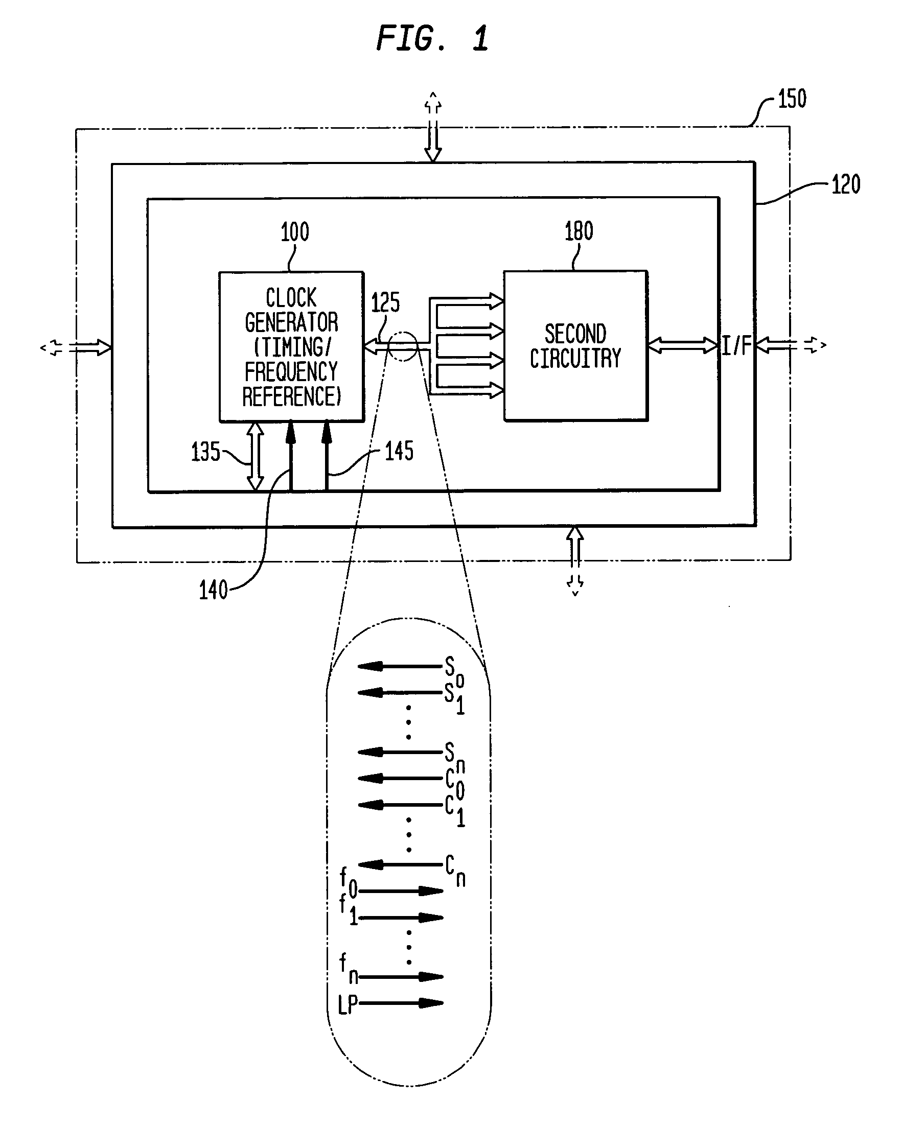
[0080]As indicated above, the various embodiments of the invention provide numerous advantages, including the ability to integrate a highly accurate (over PVT and age), low-jitter, free-running and self-referencing clock generator and / or a timing and frequency reference with other circuitry, such as illustrated in FIG. 1. FIG. 1 is a block diagram illustrating an exemplary system embodiment 150 in accordance with the teachings of the present invention. As illustrated in FIG. 1, the system 150 is a single integrated circuit, having a clock generator and / or timing / fr...


PUM


Abstract

Exemplary embodiments of the invention provide a system, method and apparatus for frequency calibration of a free-running, harmonic oscillator. A reference oscillator provides a reference frequency. An exemplary system comprises the harmonic oscillator, a frequency divider, a comparator, and a reactance modulator. The oscillator comprises a plurality of switchable reactance modules and a coefficient register, and provides an oscillation signal having an oscillation frequency. The frequency divider provides an output frequency as a fraction of the oscillation frequency. The comparator compares the output and reference frequencies and provides a comparison signal when the output frequency is not substantially equal to the reference frequency. The reactance modulator determines and provides to the coefficient register a first plurality of coefficients to control switching of a first subset of the reactance modules to increase the reactance of the oscillator when the output frequency is greater than the reference frequency, and a second plurality of coefficients to control switching of a second subset of the reactance modules to decrease the reactance of the oscillator when the output frequency is less than the reference frequency.

Description

CROSS-REFERENCE TO RELATED APPLICATIONS[0001]This application is a continuation-in-part of and claims priority to U.S. patent application Ser. No. 11 / 084,962, filed Mar. 21, 2005, inventors Michael Shannon McCorquodale, Scott Michael Pemia, and Amar Sarbbaseh Basu, entitled “Monolithic Clock Generator and Timing / Frequency Reference” (the “first related application”), which is commonly assigned herewith, the contents of which are incorporated herein by reference, and with priority claimed for all commonly disclosed subject matter, and further claims priority to U.S. Provisional Patent Application Ser. No. 60 / 555,193, filed Mar. 22, 2004, inventor Michael Shannon McCorquodale, entitled “Monolithic and Top-Down Clock Synthesis with Micromachined Radio Frequency Reference” (the “second related application”), which is commonly assigned herewith, the contents of which are incorporated herein by reference, and with priority claimed for all commonly disclosed subject matter.[0002]This appli...

Claims


Application Information

Patent Timeline
Patent Type & Authority Patents(United States)
IPC IPC(8): G01R23/00H03B5/12
CPCH03B5/04H03B5/06H03L1/00H03L1/026H03L3/00H03L7/099H03L7/24H03B5/1228H03B5/1212H03B5/124H03B2200/0038H03B2200/005H03B2200/0098H03J2200/10H03L7/06H03L7/0812H03L7/089H03L7/093H03L7/183
Inventor MCCORQUODALE, MICHAEL SHANNONPERNIA, SCOTT MICHAELKUBBA, SUNDUSBASU, AMAR SARBBASESH
Owner INTEGRATED DEVICE TECH INC
Why Eureka
Try Eureka