Data transfer control device and electronic instrument

a control device and data technology, applied in the direction of instruments, generating/distributing signals, pulse techniques, etc., can solve the problems of limited power consumption reduction and inability to perform data transfer

Inactive Publication Date: 2007-07-24
SEIKO EPSON CORP
View PDF28 Cites 35 Cited by
  • Summary
  • Abstract
  • Description
  • Claims
  • Application Information

AI Technical Summary

Problems solved by technology

However, since the high-speed serial transfer interface allows current to constantly flow through the transmitter circuit and the receiver circuit, reduction of power consumption is limited.
On the other hand, data transfer cannot be performed if the path of the constant current is cut.

Method used


Image

  • Data transfer control device and electronic instrument
  • Data transfer control device and electronic instrument
  • Data transfer control device and electronic instrument

Examples


Embodiment Construction

[0043]Embodiments of the present invention are described below.

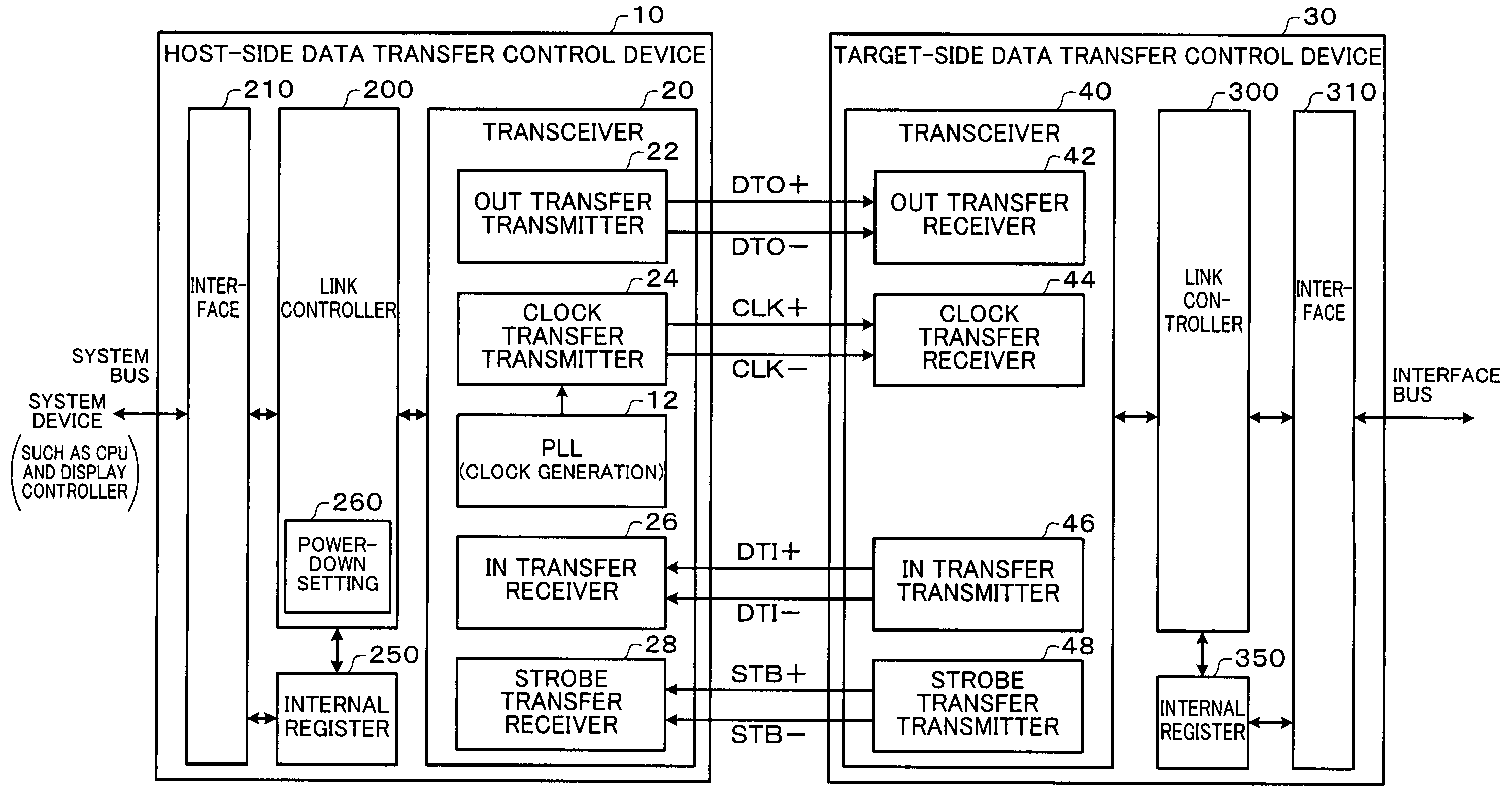
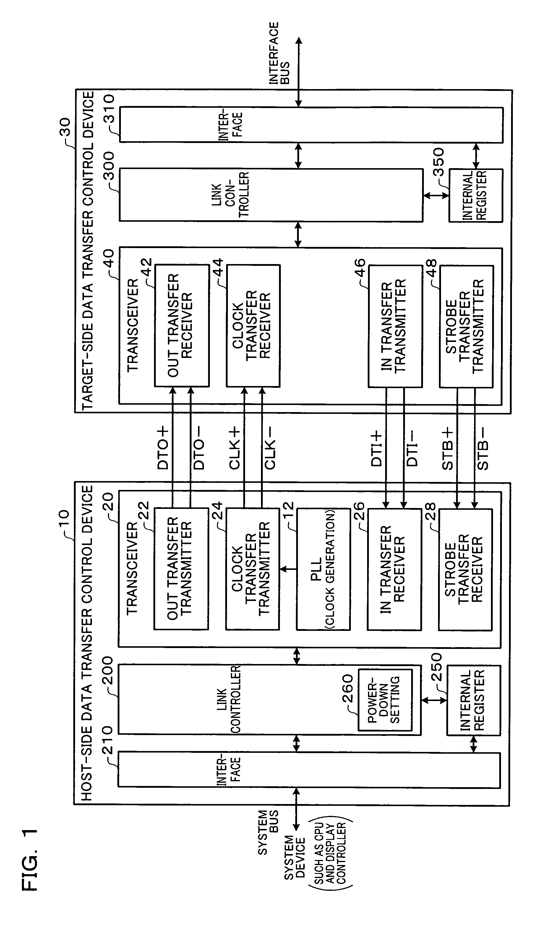
[0044]One embodiment of the present invention provides a host-side data transfer control device which performs data transfer with a target-side data transfer control device, the host-side data transfer control device including:

[0045]an OUT-transfer transmitter circuit which is connected with an OUT-transfer receiver circuit of the target-side data transfer control device through an OUT-transfer serial signal line, and transmits OUT data by driving the OUT-transfer serial signal line;

[0046]a clock-transfer transmitter circuit which is connected with a clock-transfer receiver circuit of the target-side data transfer control device through a clock-transfer serial signal line, and transmits a clock signal, which is used to sample the OUT data and is used to generate a system clock signal of the target-side data transfer control device, by driving the clock-transfer serial signal line; and

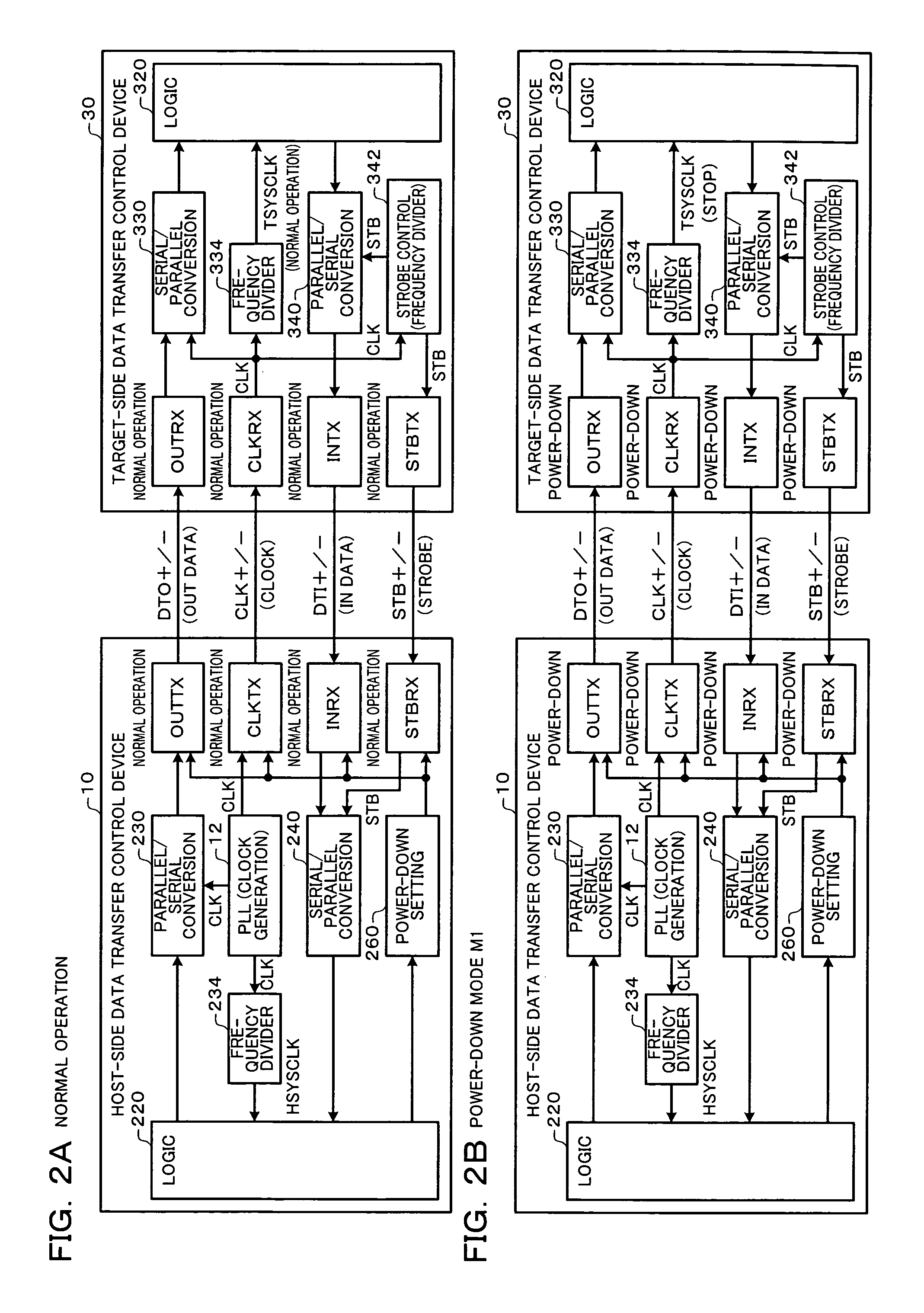
[0047]a power-down setting circuit fo...


PUM


Abstract

A data transfer control device includes an OUT-transfer transmitter circuit which transmits OUT data by driving a serial signal line, a clock-transfer transmitter circuit which transmits a clock signal CLK by driving a serial signal line, a PLL circuit which generates the clock signal CLK, and a power-down setting circuit which sets a power-down mode. In a first power-down mode, the OUT-transfer transmitter circuit is set to the power-down mode, and the clock-transfer transmitter circuit is set to the power-down mode to stop a system clock signal of a target-side data transfer control device. In a second power-down mode, the OUT-transfer transmitter circuit is set to the power-down mode without setting the clock-transfer transmitter circuit to the power-down mode.

Description

[0001]Japanese Patent Application No. 2003-314055, filed on Sep. 5, 2003, Japanese Patent Application No. 2003-314056, filed on Sep. 5, 2003, Japanese Patent Application No. 2004-14412, filed on Jan. 22, 2004, Japanese Patent Application No. 2004-14413, filed on Jan. 22, 2004, and Japanese Patent Application No. 2004-65937, filed on Mar. 9, 2004, are hereby incorporated by reference in their entireties.BACKGROUND OF THE INVENTION[0002]The present invention relates to a data transfer control device and an electronic instrument.[0003]In recent years, a high-speed serial transfer interface such as low voltage differential signaling (LVDS) has attracted attention as an interface standard aiming at reducing EMI noise or the like. In the high-speed serial transfer interface, data transfer is realized by allowing a transmitter circuit to transmit serialized data using differential signals and a receiver circuit to differentially amplify the differential signals. Japanese Patent Application...

Claims


Application Information

Patent Timeline
Patent Type & Authority Patents(United States)
IPC IPC(8): G06F1/26G06F1/32H04B1/04H04B1/10H04B1/38G06F1/04G06F3/00H03K19/00H03K19/0175H04L25/02H04L25/40H04L29/00
CPCG06F1/3203H04L25/0272H04L12/02H04L25/40H03K19/00H04L69/32
Inventor SHIBATA, YUKINARISAITO, NOBUYUKIHASEGAWA, TOMONAGAISHIDA, TAKUYA
Owner SEIKO EPSON CORP
Why Eureka
Try Eureka