Gasket cutter with changeable and reversible dies and punches

Inactive Publication Date: 2007-07-31
RAY DANIEL W
View PDF9 Cites 13 Cited by
  • Summary
  • Abstract
  • Description
  • Claims
  • Application Information

AI Technical Summary

Benefits of technology

[0023]Accordingly, it is an object of my version of the invention to provide a low-cost, easy-to-manufacture, and easy-to-market gasket cutter with changeable and reversible d

Problems solved by technology

Even though these designs may be suitable for the specific individual purposes to which they address, they would not be suitable for the purposes of the present version of the invention as such designs are elaborate in design, cumbersome to use, and ar

Method used


Image

  • Gasket cutter with changeable and reversible dies and punches
  • Gasket cutter with changeable and reversible dies and punches
  • Gasket cutter with changeable and reversible dies and punches

Examples


Embodiment Construction

[0126]A detailed description of the preferred embodiment is provided herein. It is to be understood, however, that the present invention may be embodied in various forms. Therefore, specific details disclosed herein are not to be interpreted as limiting, but rather as a basis for the claims and as a representative basis for teaching one skilled in the art to employ the present invention in virtually any appropriately detailed system, structure or manner.

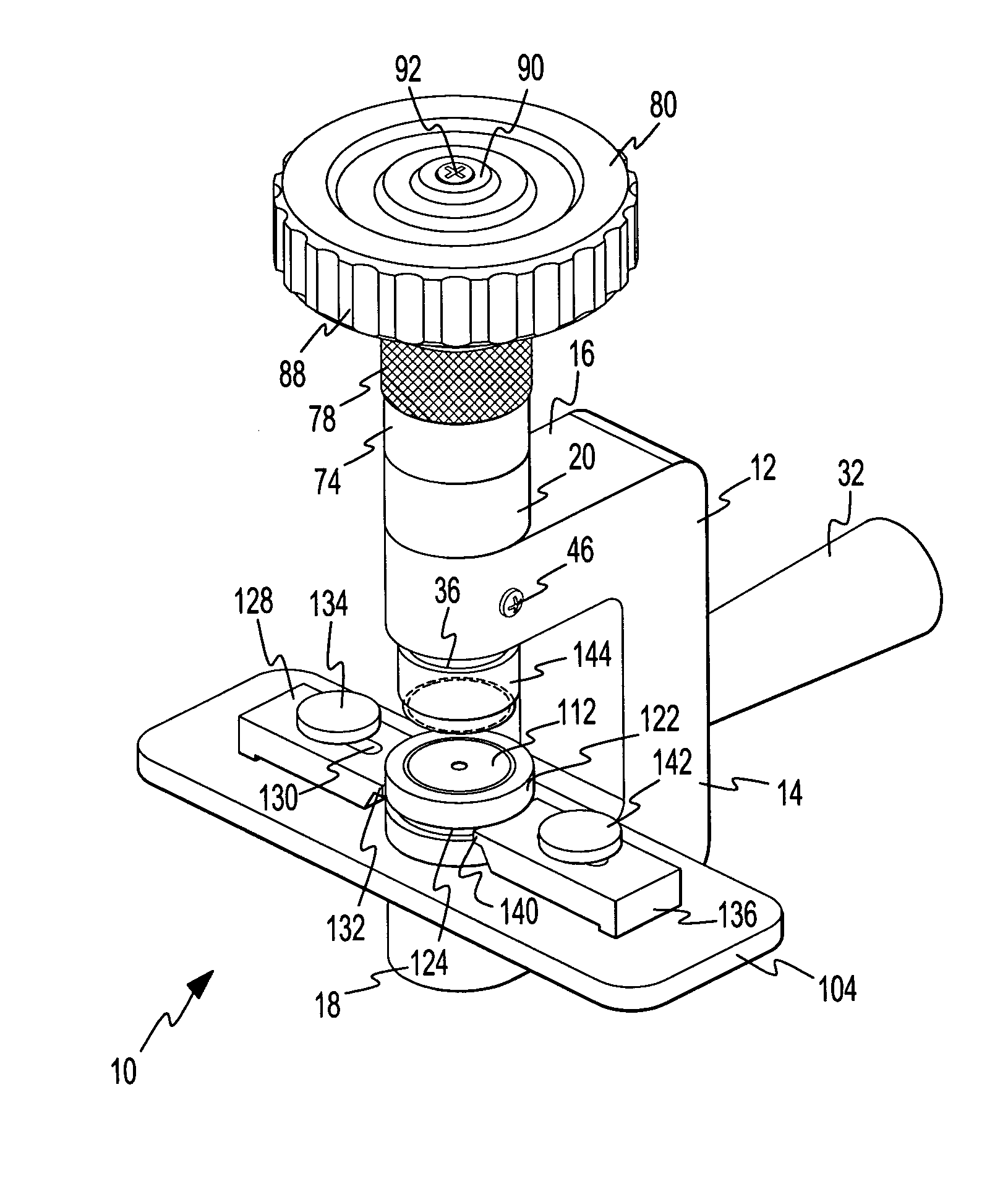
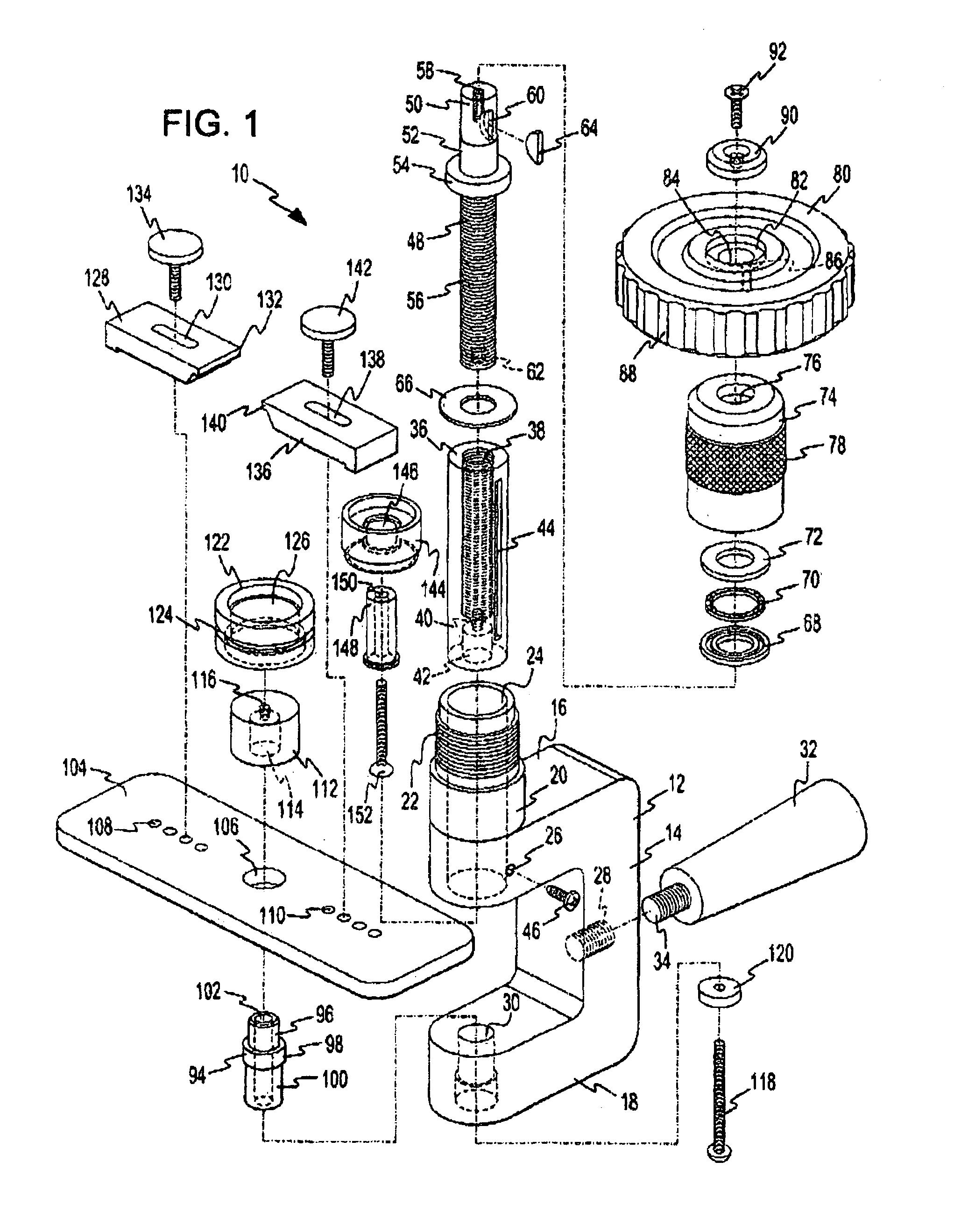
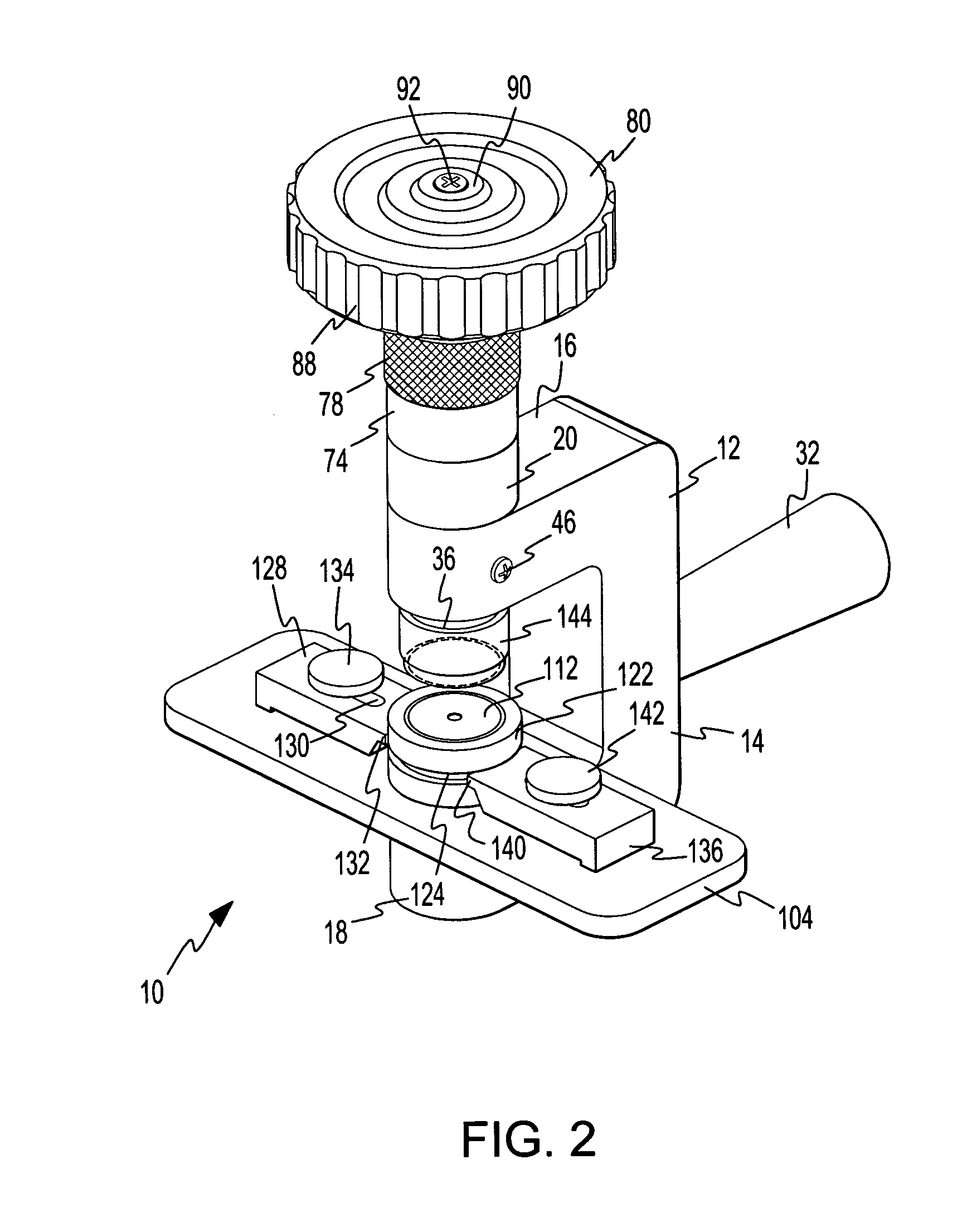
[0127]Referring now to the drawings and, in particular, to FIG. 1 wherein there is illustrated a typical embodiment of the gasket cutter with changeable and reversible dies and punches 10. The present version of the invention 10 consists of a body 12 having a side member 14, top arm member 16, and opposed bottom arm member 18. The side member 14 is connected at a first end thereof to a first end of the top arm member 16 and at a second end thereof to a first end of the bottom arm member 18. The top 16 and bottom 18 arm members are di...


PUM

PropertyMeasurementUnit
Diameteraaaaaaaaaa
Sizeaaaaaaaaaa
Distanceaaaaaaaaaa

Abstract

A gasket cutter with changeable and reversible dies and punches including a body having upper and lower opposed arm members, a cylindrical member slidingly engaged within said upper arm member to be raised and lowered by rotation of a handle attached to the cylindrical member, and a platen releasably secured to the lower arm member. A cylindrical punch and a ring die surrounding the punch are attached to the platen. The ring die includes a first and second inner diameter at first and second ends thereof creating with said punch a first and second gap, respectively. A reversible punch die having first and second opposed cutting edges is releasably attached to the cylindrical member so that the first or second cutting edge of the punch die descends into the first or second gap, thereby cutting a ring gasket of a desired size from a sheet of gasket material.

Description

BACKGROUND OF THE INVENTION[0001]This version of the invention is concerned with the field of gasket cutters. More specifically, this version of the invention is concerned with a gasket cutter having changeable and reversible dies and punches so as to form gaskets with a variety of thicknesses and diameters.[0002]1. Prior Art[0003]A variety of tools and devices are available for creating gaskets from a sheet of gasket material. The means and methods of forming a gasket usually involve a multi-step process whereby a hole pattern is first formed in the gasket material. The gasket material is then removed from the tool or device after the pattern is formed, and the hole is then punched as indicated by the pattern. This process is time-consuming, laborious, and subject to errors. For instance, if the pattern and punching are not formed carefully, errors and misaligned or incorrectly-sized gaskets may be formed, resulting in a waste of time, effort, and gasket material.[0004]This process...

Claims


Application Information

Patent Timeline
IPC IPC(8): B26F1/02B26F1/14
CPCB26D5/10B26D7/2614B26F1/3846B26D2007/2607Y10S83/955Y10T83/9476Y10T83/9428Y10T83/9425Y10T83/8847
Inventor RAY, DANIEL W.
Owner RAY DANIEL W
Why Eureka
Try Eureka