Multi-function well servicing vehicle

a multi-functional, well-maintained technology, applied in the direction of fluid removal, drilling machines and methods, construction, etc., can solve the problems of large, heavy, and poor suitability of prior-art drilling rigs for joining pipes, and achieve cost and weight saving, cost saving, and additional cost and weight saving

Inactive Publication Date: 2007-07-31
MRBD
View PDF10 Cites 28 Cited by
  • Summary
  • Abstract
  • Description
  • Claims
  • Application Information

AI Technical Summary

Benefits of technology

[0032]Advantageously, it was realized by the within inventors that the steps of well servicing provided by the equipment of this vehicle are sequential steps, and typically do not overlap in time. Thus if all equipment was to be hydraulically powered, the hydraulic pressure needed to operate the various equipment need not be the sum of the required individual equipment pressures, but need only be the single maximum pressure needed to operate a single individual equipment. Thus it was realized that considerable weight-saving and cost saving can be accomplished by being able to use a single hydraulic pump, and further, one that is powered by the vehicle's engine and not by an on-board auxiliary motor. In addition, by providing all equipment be hydraulic, as opposed to having such equipment powered by mixed means (e.g. electrical, hydraulic, direct drive from auxiliary internal combustion motor, or combination thereof, additional cost and weight savings can be recognized by eliminating the need to provide an electrical generator or auxiliary internal combustion motor for some of the equipment, such as winches. Thus by using hydraulic power for each of the implements, and a single hydraulic pump to supply each of the equipment, namely the power tongs, hydraulic pistons, levelling jacks, and first, second and third winches, considerable cost and weight savings can be realized.

Problems solved by technology

The swabbing operation frequently needs to be carried out a number of times in order that the well be as underbalanced as possible.
Typically, these prior art drilling rigs are relatively large and heavy, particularly where they are adapted for drilling deeper wells (i.e. wells of more than 1500 to 3000 m in depth).
In the prior art, due to the size and complexity of the above prior art drilling rigs, these units are usually only adapted for the drilling of the well.
Disadvantageously, however, such “second generation” service rig vehicles needed at least one additional service vehicle having auxiliary equipment such as hydraulic power tongs for the power handling and threading of jointed pipe during the TCP operation.
While U.S. Pat. No. 6,003,598 discloses that it may be used for manipulating joined pipe (as opposed to CT) if need be, and indeed discloses winch 46 for such purpose, disadvantageously vehicle 22 of U.S. Pat. No. 6,003,598 clearly is poorly suited to insertion of jointed pipe.

Method used


Image

  • Multi-function well servicing vehicle
  • Multi-function well servicing vehicle
  • Multi-function well servicing vehicle

Examples


Embodiment Construction

[0070]In all figures, for consistency, identical components are identified with identical reference numerals.

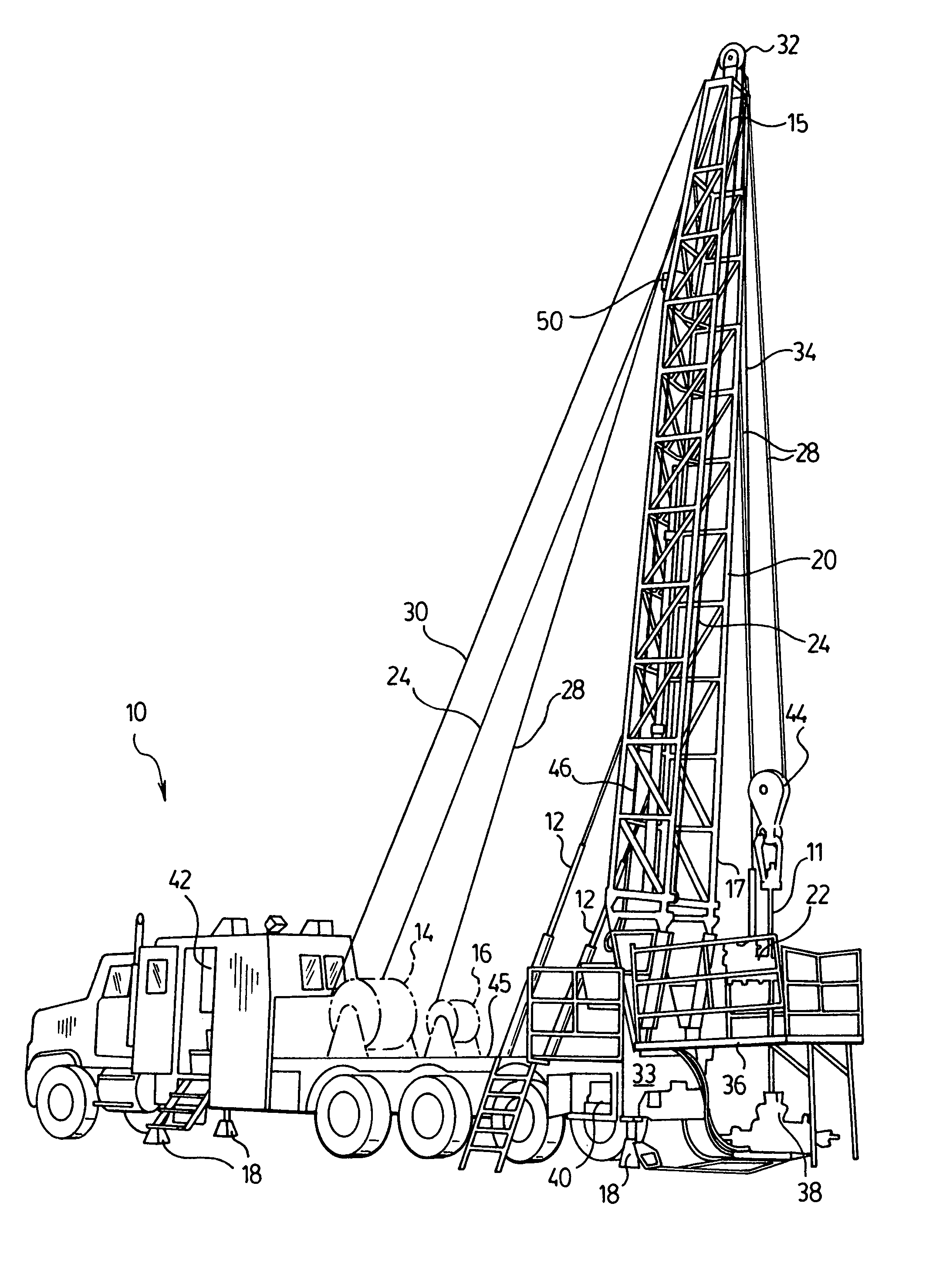
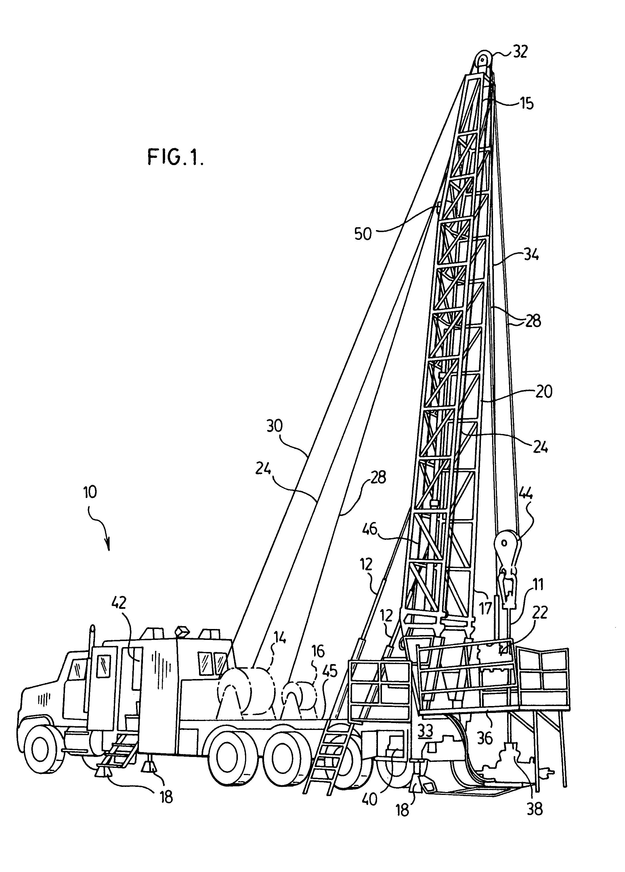
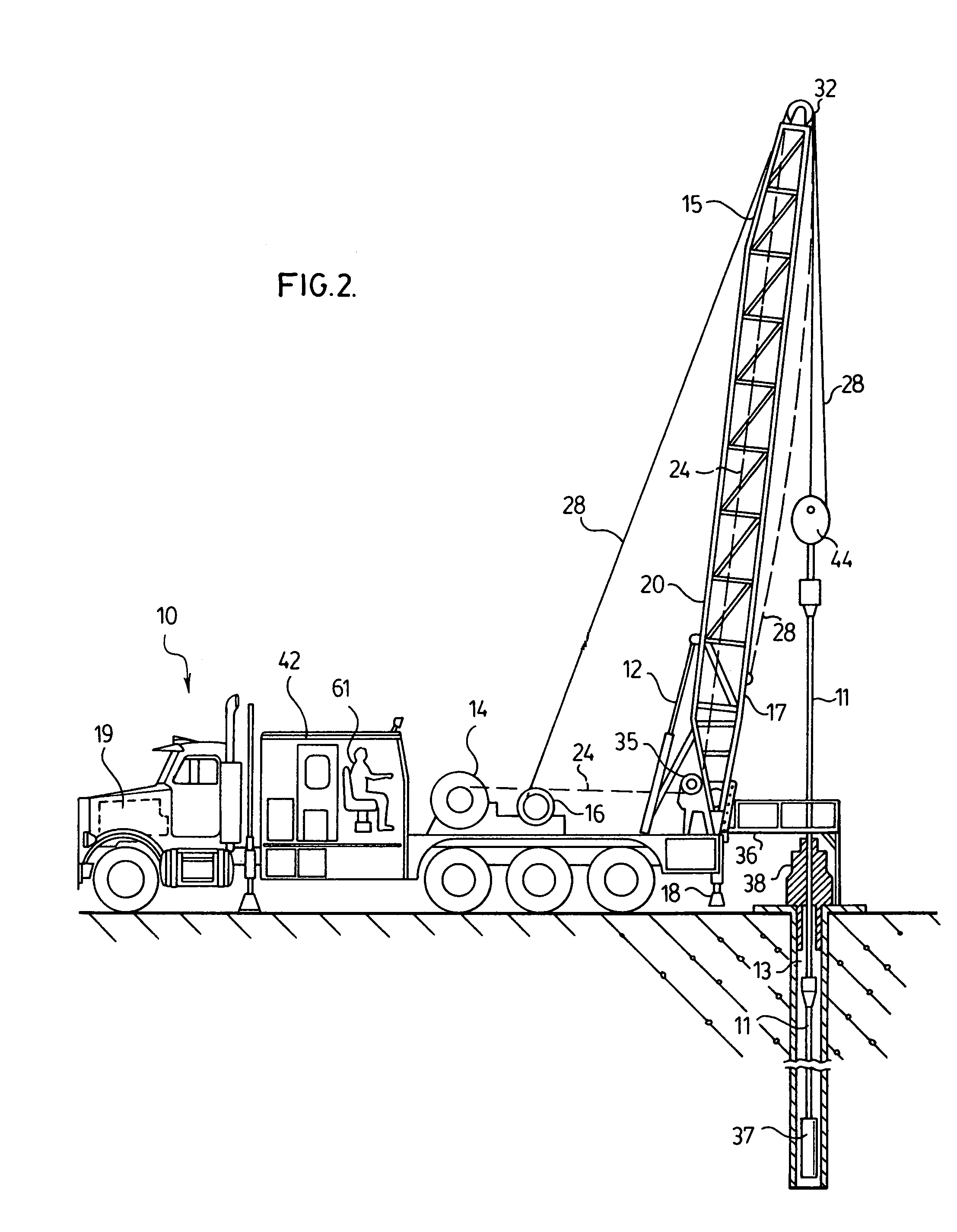
[0071]With reference to FIGS. 1-3, an embodiment of the mobile well servicing vehicle 10 of the present invention is shown. Vehicle 10 is adapted to conduct insertion of jointed pipe 11 into a well 13, and to further carry out at least one additional well-servicing step including logging, swabbing, and / or perforating of the inserted tubing 11.

[0072]Vehicle 10 possesses an elongate mast or derrick 20, having a top end 15 and a bottom end 17, which is pivotably coupled to the bed of the vehicle 10 proximate a rearmost end 33 of vehicle 10, as shown in FIGS. 1-3.

[0073]Derrick 20 is pivotable from a substantially horizontal transport position, as shown in each of FIGS. 4 & 5, to a substantially vertical operable position, as shown in FIGS. 1-3, by means of two hydraulic pistons 12 which serve to raise and lower derrick 20. Because derrick 20 may in some cases be used in a slightl...


PUM


Abstract

A mobile vehicle for inserting jointed pipe into a well, having a derrick and hydraulic rams to raise and lower same, adapted to conduct additional operations which will allow a well to be completed by this vehicle alone. Three winches are provided, a first to raise and lower power tongs to manoeuvre and thread jointed pipe, a second situate on the bed of the vehicle to raise and lower jointed tubing, and a third likewise mounted on the bed of the vehicle on which a conductive wireline is wound, for raising and lowering logging and swabbing devices in the well. Levelling jacks are provided at four corners of the vehicle to permit levelling of the vehicle and alignment of jointed pipe with the borehole of the well. Each of the rams, power tongs, levelling jacks, first, second, and third winches are hydraulically powered, preferably by a single pump, as each of the aforementioned devices are not operated at the same time but sequentially.

Description

FIELD OF THE INVENTION[0001]The present invention relates to equipment for completing and servicing oil and gas wells, and in particular relates to a multi-function mobile rig vehicle capable of carrying out a number of well completing and servicing tasks, including the insertion of jointed (but not continuous) pipe into said wells.BACKGROUND OF THE INVENTION AND DESCRIPTION OF THE PRIOR ART[0002]Typically, when an oil or gas well has been drilled, a number of further steps are required to complete the well to ready it for production. A logging operation, a swabbing operation, and an operation involving insertion of pipe or tubing into the well, and finally a perforation step to perforate said tubing, typically are additional steps required to ready a well for production.[0003]The logging step requires the lowering of a logging instrument into the drilled well. The logging instrument is an elongate cylindrical device that is typically lowered from a well-servicing vehicle via an ele...

Claims


Application Information

Patent Timeline
Patent Type & Authority Patents(United States)
IPC IPC(8): E21B19/22
CPCE21B7/024
Inventor CUNNINGHAM, BRIANJOHANSON, DAVEMCPHEDRAN, DUNCANDARLING, BILLGOSS, BARRYMAYZUS, ILYAEIRICH, GARYSLANEY, RUDY
Owner MRBD
Why Eureka
Try Eureka