Vacuum sander

Inactive Publication Date: 2007-07-31
VOLYAR MYKHAYLO
View PDF22 Cites 38 Cited by
  • Summary
  • Abstract
  • Description
  • Claims
  • Application Information

AI Technical Summary

Benefits of technology

[0018]Accordingly, it is an object of the present invention to overcome these and other drawbacks of the prior art by providing a novel convenient to use vacuum sand

Problems solved by technology

However, in most cases after a concrete structure, such as a ceiling has been cast and the mold removed therefrom, the surface of the concrete ceiling is rough due to inconsistencies in the surface of the molds and indentations formed by the seams between adjacent molds.
Although there have been ceiling grinding machines known in the prior art, these machines have been unsatisfactory in various manners.
First, typically these grinding machines utilize abrading discs, cups or belts which wear out quickly, necessitating expensive and time consuming replacement, and do not provide a very strong abrading force to the concrete.
However, this flexible cable is subject to intense frictional forces and therefore wears out quickly.
Moreover, the use of single-phase electrical motors to run such abrading devices restricts the device to one rotational speed, thereby reducing the versatility of the device.
Another problem with prior art machines is their poor maneuverability.
This obviously causes interfere

Method used


Image

  • Vacuum sander
  • Vacuum sander
  • Vacuum sander

Examples


Embodiment Construction

[0031]A detailed description of the present invention follows with reference to accompanying drawings in which like elements are indicated by like reference letters and numerals.

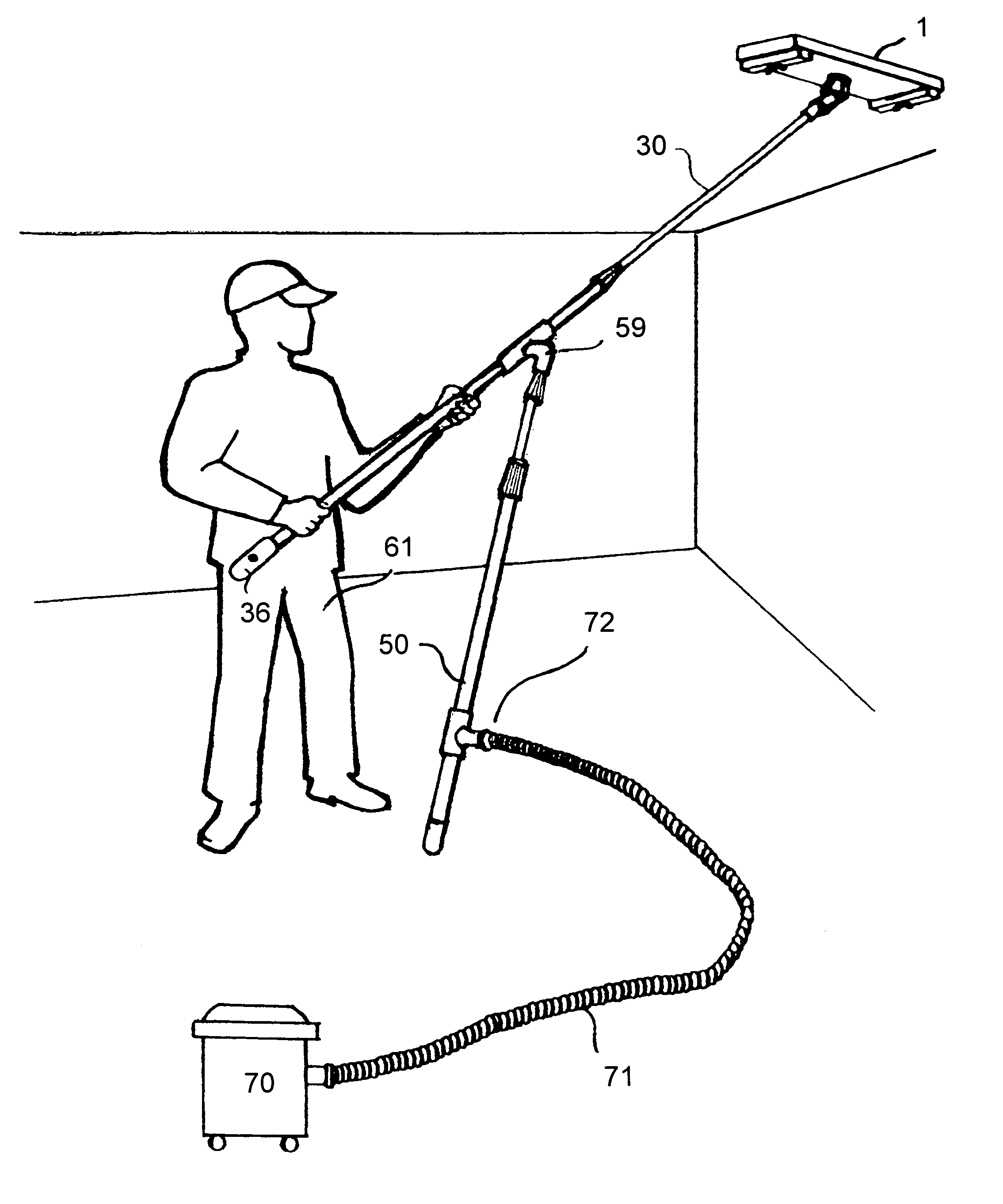
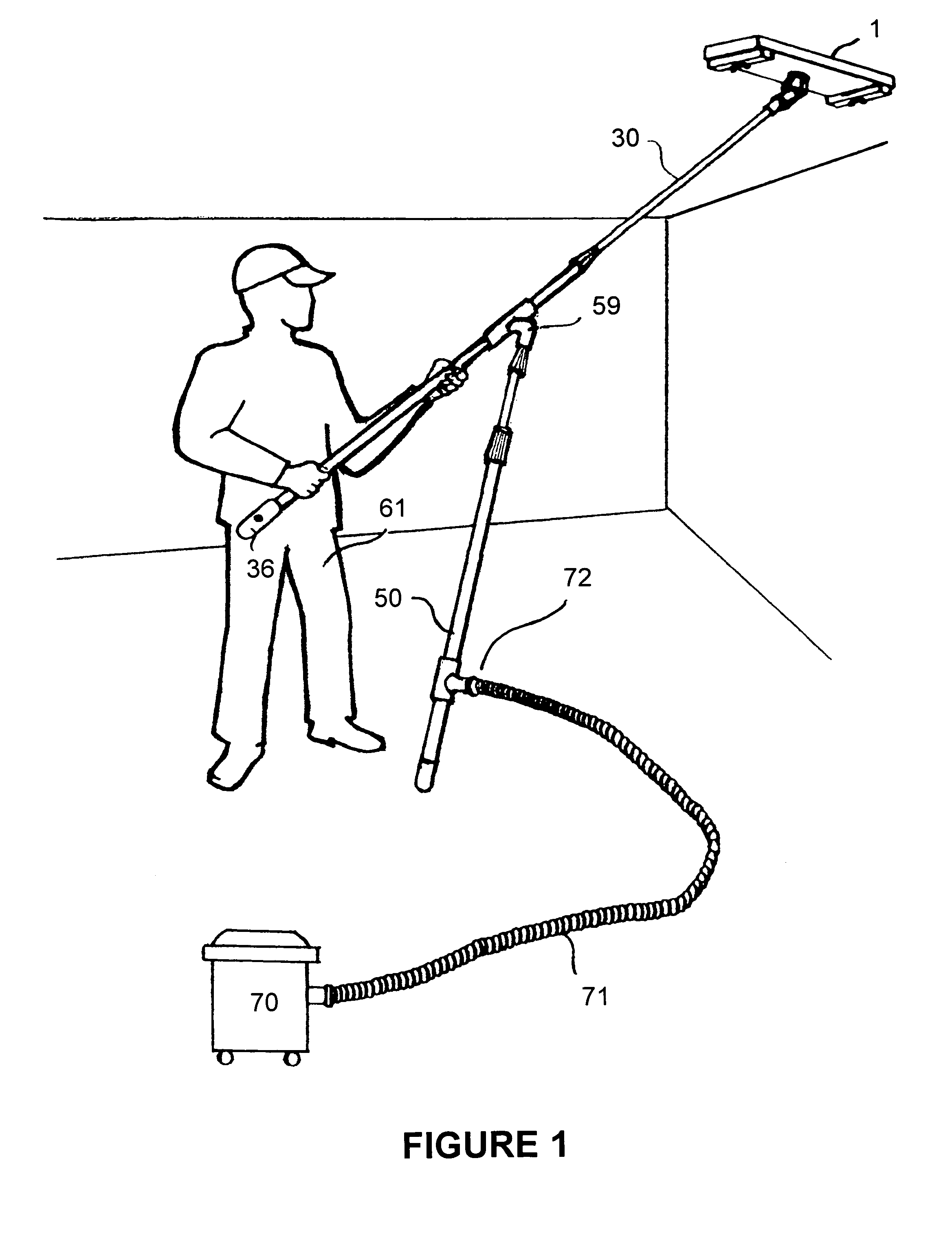
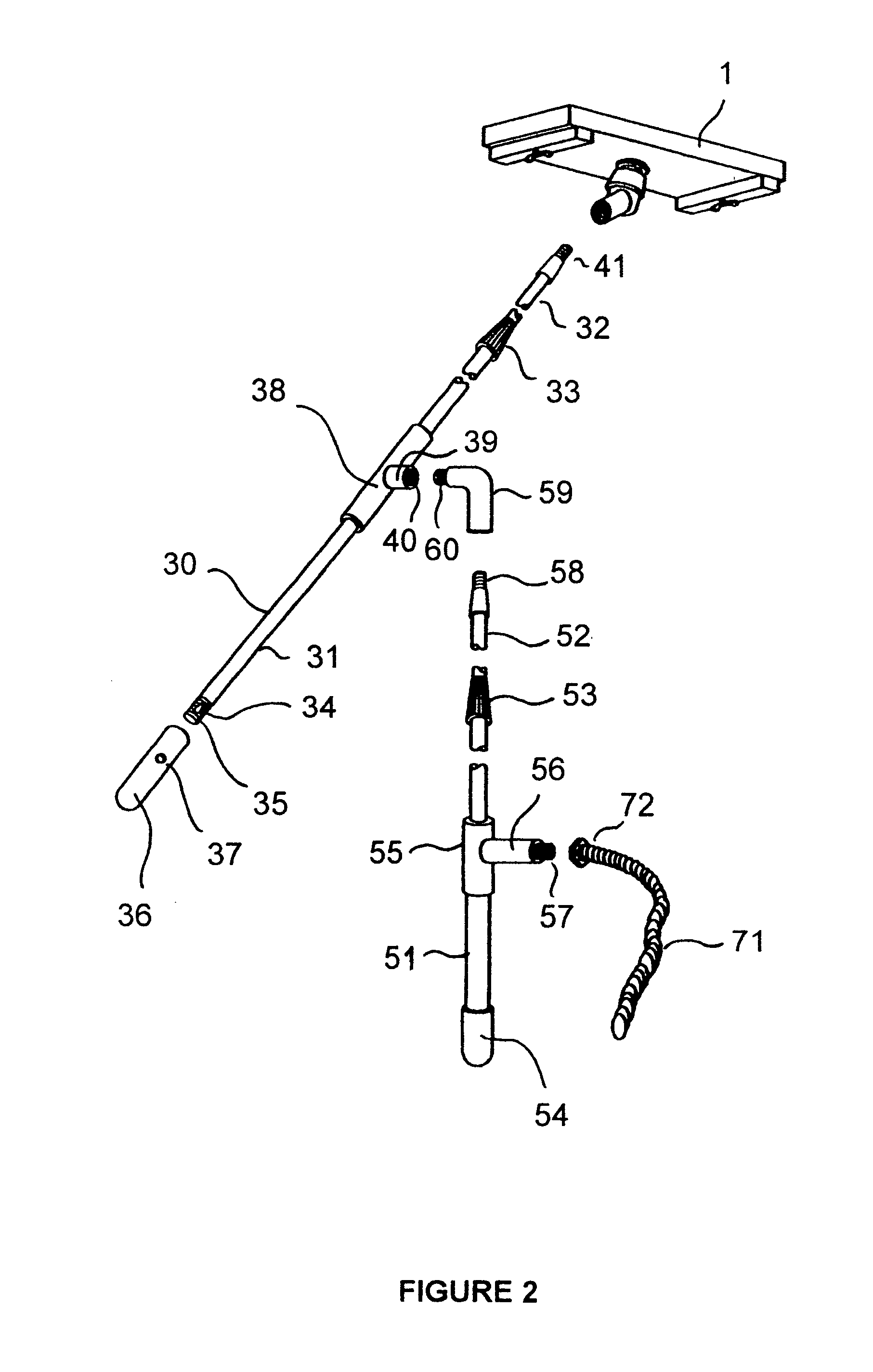
[0032]FIG. 1 and FIG. 2 show the general and exploded views of the sander of the present invention. The device consists of the following key elements: the main pole 30 is extending from the operator 61 to support the sanding means 1 at its distal end such that it can swivel about it. Support pole 50 (See FIG. 1) is based on the floor of the building and is rotatably attached to the middle section of the main pole 1 through an angle connector 59. Vacuum attachment 72 allows connecting the vacuum 70 through the vacuum hose 71 to the device of the invention.

[0033]Vacuum-assisted sanding means 1 can be designed to be similar to any known sanding means described in the above referenced patents of the prior art as long as it is equipped with vacuum-assisted dust removal means. In the most preferred embodiment of t...


PUM


Abstract

A vacuum-assisted pole sander includes a sanding means attached at the end of the main pole, which in turn is supported in its middle section by a support pole. Both the support pole and the main pole are hollow and adjustable in length. The vacuum is transmitted from the sanding means of the device through the main pole to the vacuum connector in the supporting pole such that a vacuum can be attached on to ensure dust removal during operation. The combination of the support pole and the main pole is designed in such a way that the entire device is supported on the floor of the building under construction while allowing the operator to move it easily back and forth to achieve sanding of the ceiling. The support pole has a non-slip cap on its lower end and an angle connector on the other end. The angle connector is rotatably attached to the main pole such that it ensures the ability to swivel and at the same time provides a fluid communication between the inside portions of both the main pole and the support pole. The support pole is equipped with a vacuum attached for connecting to the suction means. The lower end of the main pole is equipped with vacuum strength adjustment means.

Description

BACKGROUND OF THE INVENTION[0001]The present invention relates generally to abrading or grinding devices. More particularly, the device of the invention relates to a ceiling vacuum-assisted grinding apparatus for use in surfacing of drywall and concrete ceilings.[0002]Drywall and concrete have now become very popular materials used in the construction of buildings, mainly because of their strength and durability and because molding and casting technology has advanced greatly in recent years. However, in most cases after a concrete structure, such as a ceiling has been cast and the mold removed therefrom, the surface of the concrete ceiling is rough due to inconsistencies in the surface of the molds and indentations formed by the seams between adjacent molds. Thus, it is necessary to dress or smooth poured concrete ceilings by grinding the exposed surfaces of the ceiling. The same is generally true about the drywall ceilings although they require substantially less grinding to smooth...

Claims


Application Information

Patent Timeline
IPC IPC(8): B24B23/00
CPCB24B7/184B24B55/10B24D15/023
Inventor VOLYAR, MYKHAYLO
Owner VOLYAR MYKHAYLO
Why Eureka
Try Eureka