
Energy filter image generator for electrically charged particles and the use thereof

a technology of energy filter and electrically charged particles, applied in the direction of particle separator tubes, energy spectrometers, isotope separation, etc., can solve the problems of limiting the local resolving power, increasing background noise, and 3 m image field edge image error

Active Publication Date: 2007-07-31
OMICRON NANO TECH +1
View PDF11 Cites 6 Cited by
  • Summary
  • Abstract
  • Description
  • Claims
  • Application Information

AI Technical Summary

Benefits of technology

This patent describes an energy filter used in various measurement tools such as timers or analyzers. One important benefit of this filter is its ability to eliminate any variations in timing between different measurements made with the same instrument.

Problems solved by technology

The technical problem addressed in this patent is how to create an accurate and reliable analysis of samples using an electron accelerator. The issue arises because the position of the detector changes depending upon the location of the incident electron beam, leading to errors if uncorrected. Additionally, the optical elements within the machine may cause distortion and reduce the overall quality of the captured image. Various solutions are presented below, including the use of multiple detectors, symmetrical arrangements of components, and precise alignment techniques.

Method used


Image

  • Energy filter image generator for electrically charged particles and the use thereof
  • Energy filter image generator for electrically charged particles and the use thereof
  • Energy filter image generator for electrically charged particles and the use thereof

Examples


Embodiment Construction

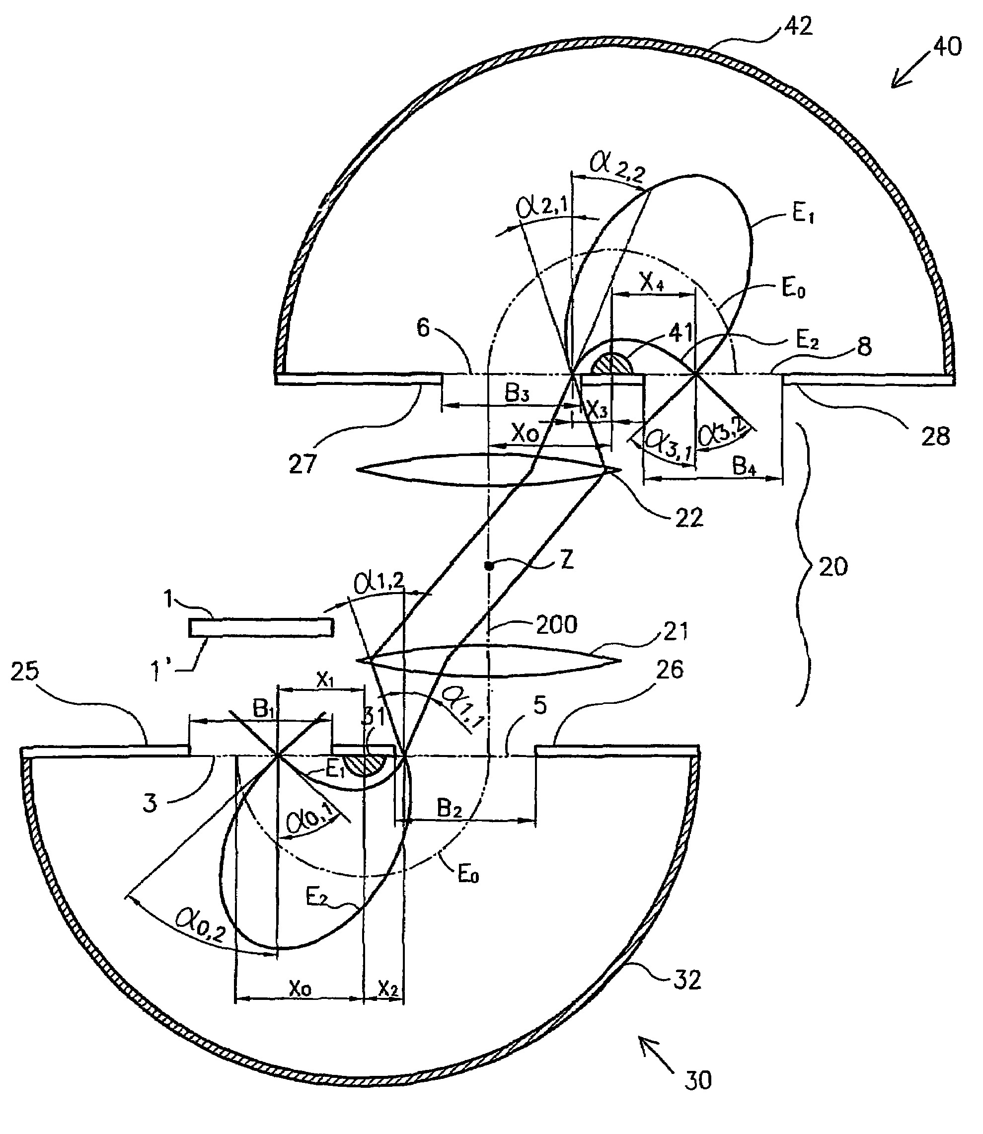
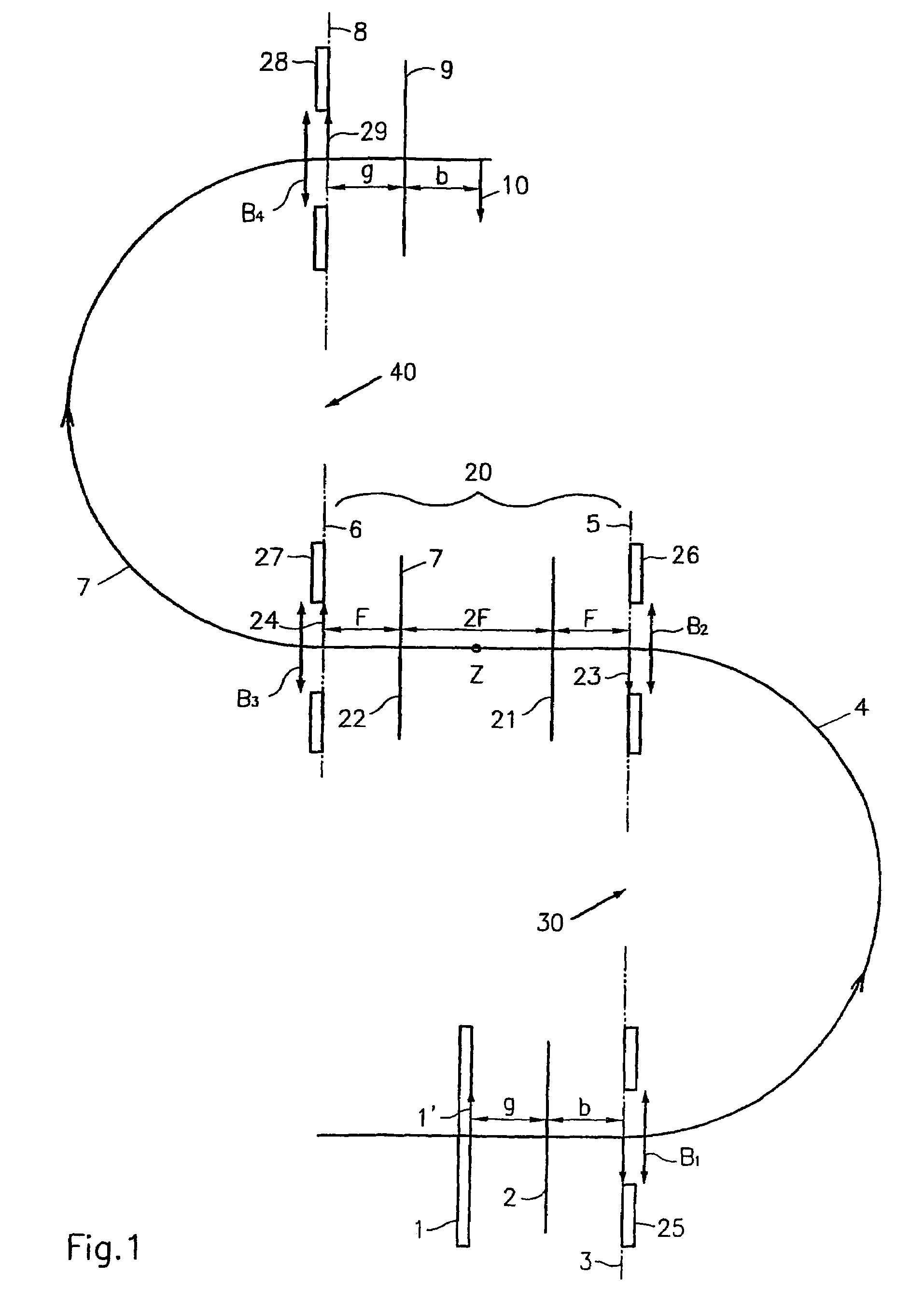
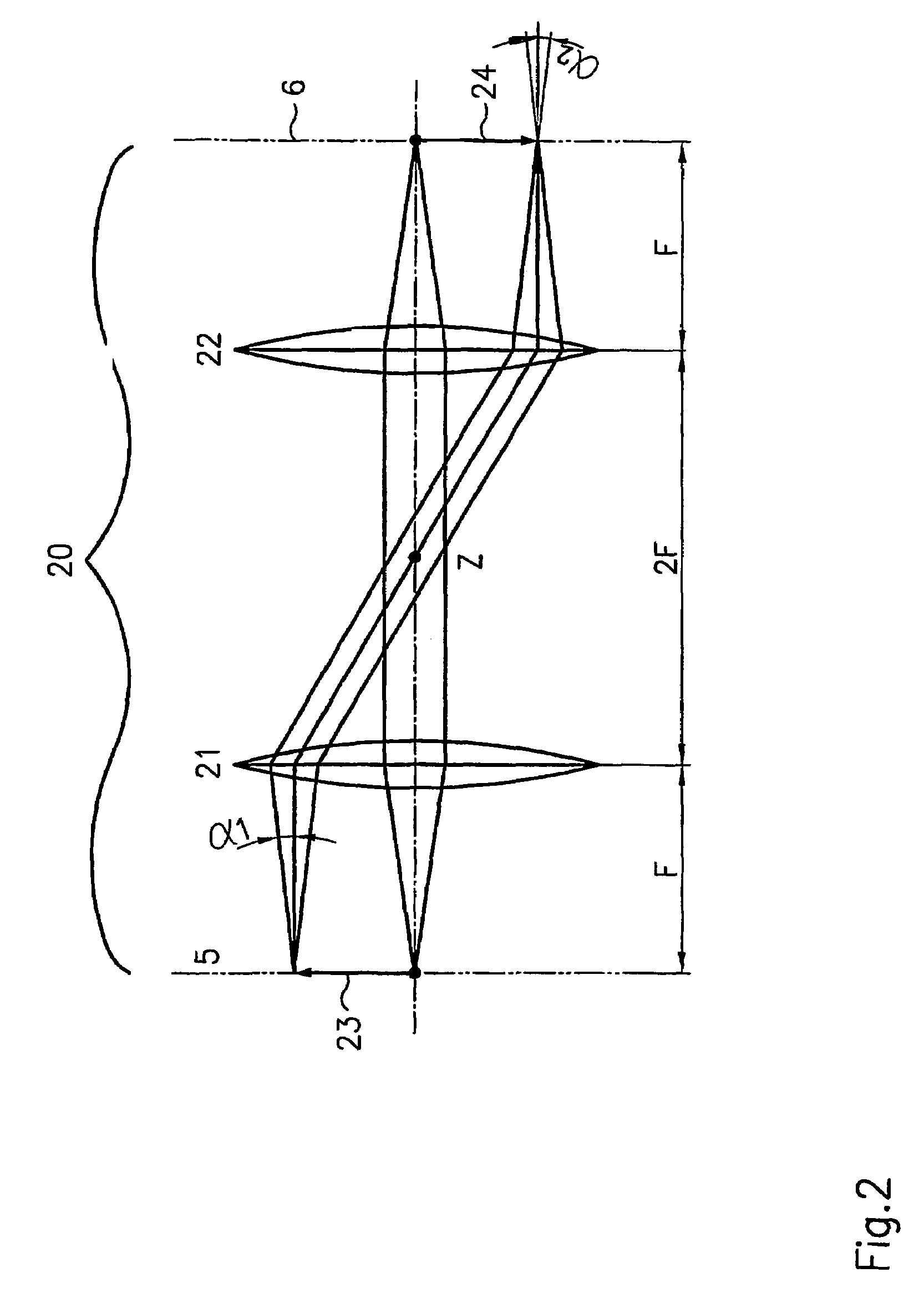
[0077]FIG. 1 shows a schematic cross-sectional diagram of an energy filter, which has two hemispherical analyzers 30 and 40, between which a transfer lens device 20 is located. The two energy analyzers 30, 40 together with the transfer lens device 20 are set up in such a way that the beam path lies in a plane and has the shape of an “S”.

[0078]The overall arrangement has radial symmetry with respect to the center Z of the transfer lens device 20; the radial symmetry is two-fold.

[0079]The electrons curve to the left in the first energy analyzer 30, and after they have passed through the transfer lens device 20, they curve to right in the second energy analyzer 40. This means that the two energy-dispersive planes 33, 43 of the two energy analyzers are rotated by the angle β=180° with respect to each other (see FIG. 4).

[0080]FIG. 1 shows only the center beam paths 4 and 7 of the electrons in the first and second energy analyzers. The energy filter has image-generating properties while a...


PUM


Abstract

The invention relates to an energy filter image generator for filtering electrically charged particles. The inventive energy filter comprises at least two toroidal energy analysers (30, 40) arranged one inside the other. A transfer lens device (20) is disposed between the plane of emergence (5) of the first energy analyser (30) and the plane of incidence of the second energy analyser (40), thereby making it possible to obtain the perfect energy filtered reproduction of the surface (1′) of a sample on a detector (10).

Description


Claims


Application Information

Patent Timeline
Owner OMICRON NANO TECH
Learn More