Rotary electric machine comprising a stator and two rotors

a technology of rotary electric machines and rotors, which is applied in the direction of magnetic circuit rotating parts, magnetic circuit shape/form/construction, transportation and packaging, etc., can solve the problem of relatively complicated machine manufacturing, and achieve the effect of reducing the cantilevered length of the stator and the rotors and duplicated structures

Inactive Publication Date: 2007-07-31
MOTEURS LEROY SOMER
View PDF18 Cites 53 Cited by
  • Summary
  • Abstract
  • Description
  • Claims
  • Application Information

AI Technical Summary

Benefits of technology

[0031]For machines having a relatively large axial dimension, it may prove desirable to duplicate the structure so as to reduce the cantilevered length of the stator and the rotors.

Problems solved by technology

Such a machine is relatively complicated to manufacture.

Method used


Image

  • Rotary electric machine comprising a stator and two rotors
  • Rotary electric machine comprising a stator and two rotors
  • Rotary electric machine comprising a stator and two rotors

Examples


Embodiment Construction

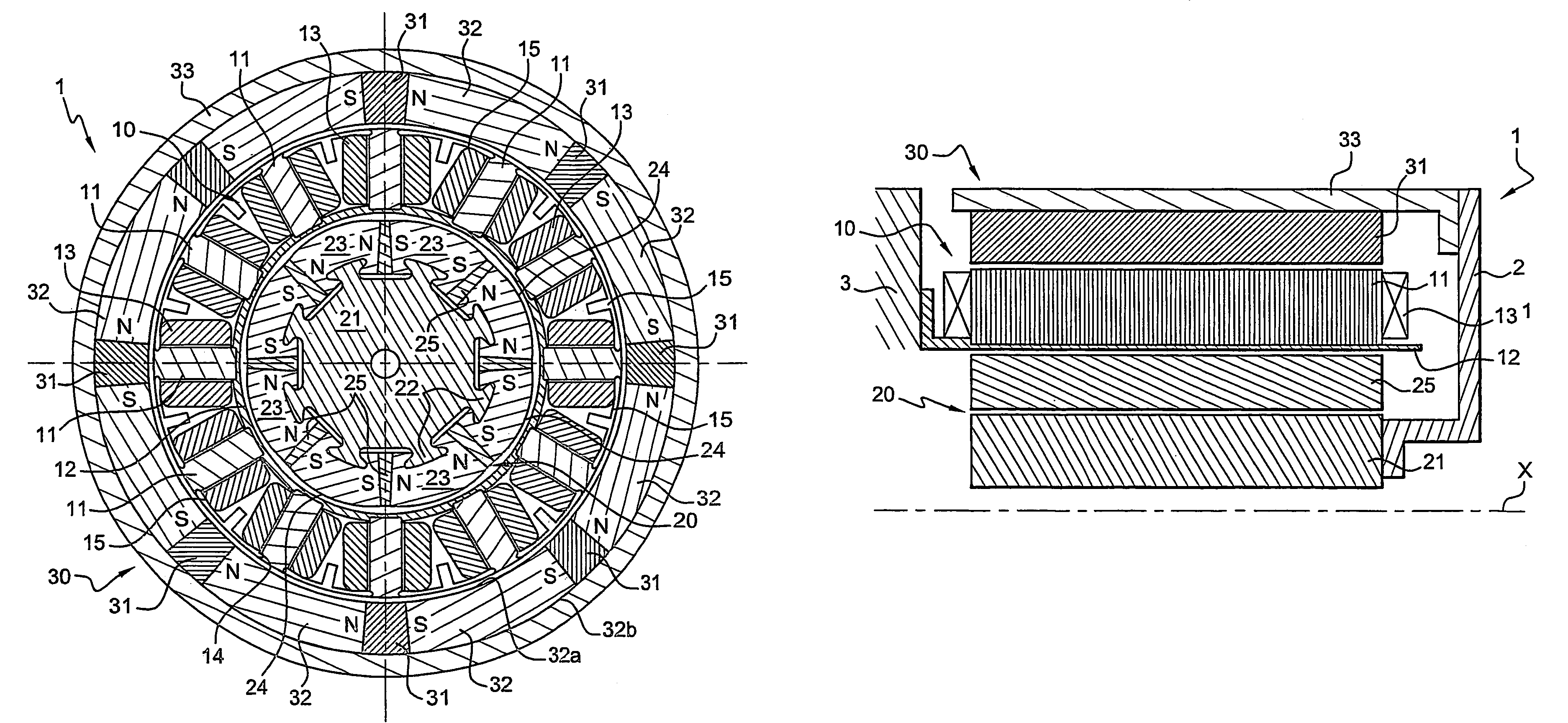
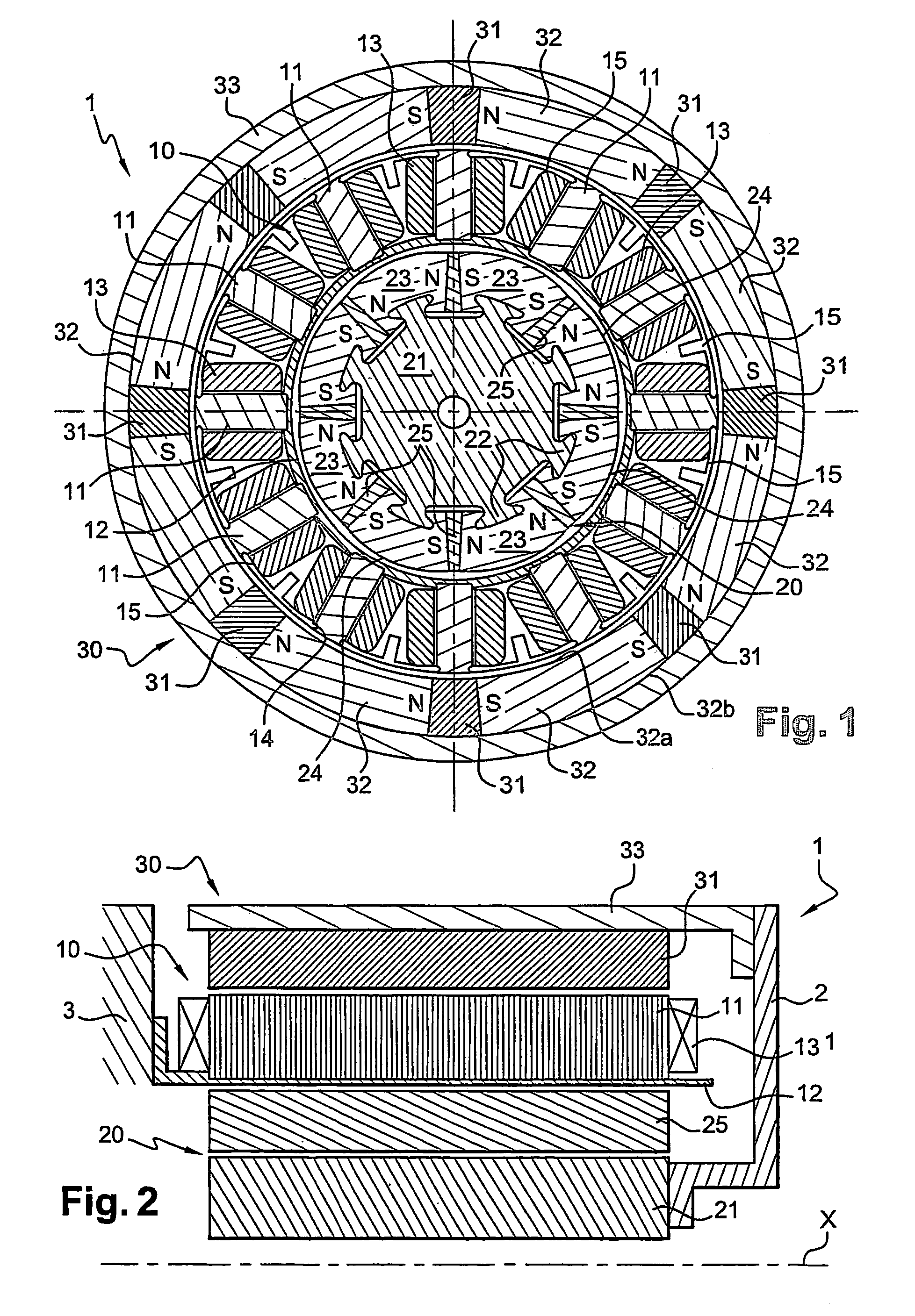
[0044]The electrical machine 1 shown in FIGS. 1 and 2 comprises a stator 10, an inner rotor 20 and an outer rotor 30 that are fastened together by a mechanical linkage 2 between them.

[0045]The stator 10 has a plurality of teeth 11 formed by a stack of magnetic laminations electrically isolated from one another, these teeth being fastened to a support piece 12 made of a nonmagnetic material, for example a nonmagnetic steel or aluminum, or made of an insulating material.

[0046]The support piece 12 is fastened, in the example described, to a frame 3 of the machine, as shown schematically in FIG. 2.

[0047]In the example in question, the teeth 11 are fastened via their radially innermost end to the support piece 12, which has a generally tubular shape. The teeth 11 may be fastened by any means to the support piece 12, for example they may be welded thereto.

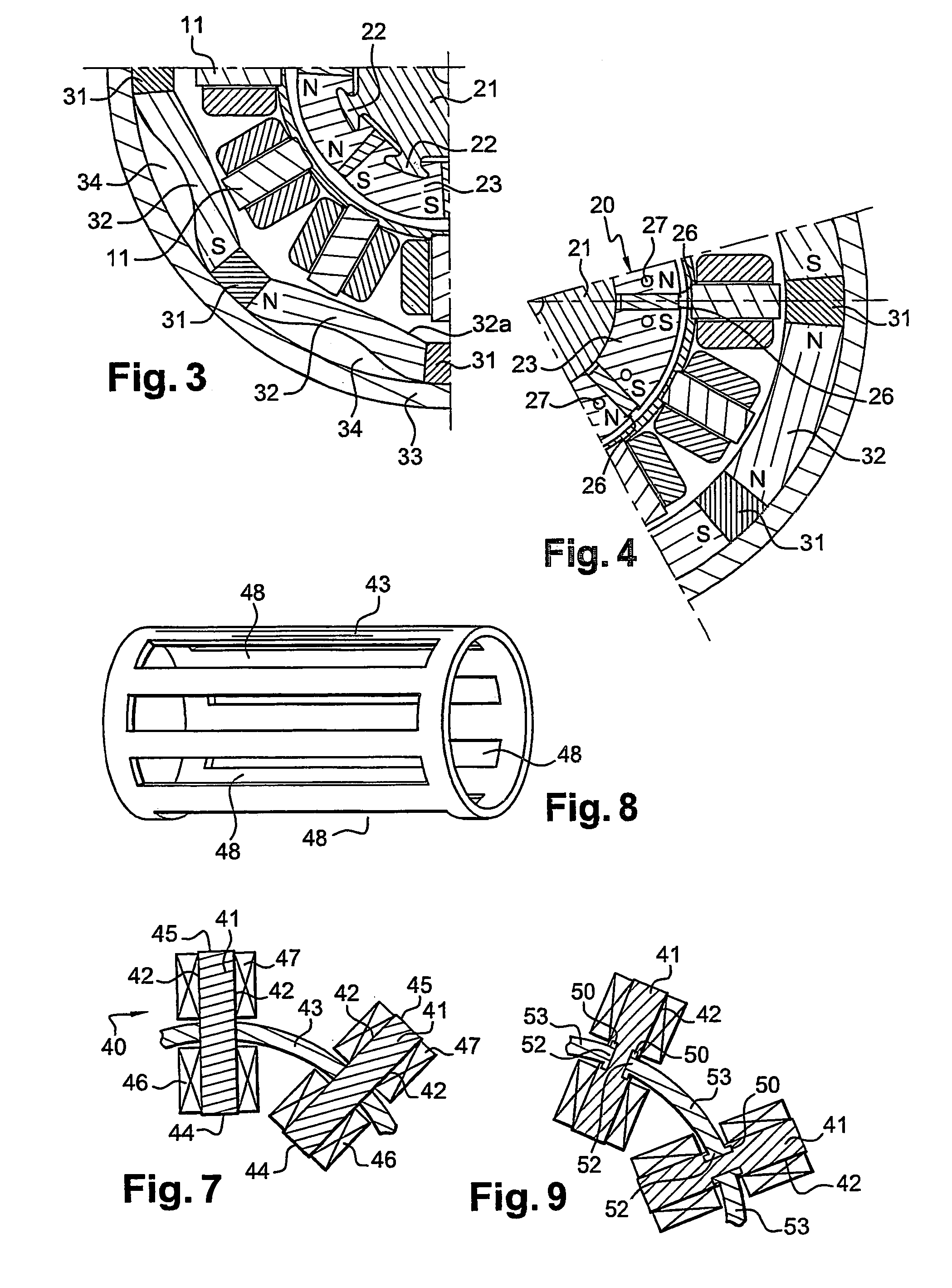
[0048]Each tooth 11 carries an individual coil 13, which comprises one or more electrical conductors wound around the axis of the corre...


PUM


Abstract

The invention relates to an electric machine comprising a stator (10, 40) provided with a plurality of teeth (11, 41), each tooth supporting at lest one individual coil (13, 46, 47), an external rotor (30) which is radially arranged outside the stator and provided with constant magnets, an internal rotor (20) radially arranged inside the stator, provided with constant magnets and connected to the external rotor (30). At least one of the external (30) and internal (20) rotors is disposed in a flux concentration.

Description

BACKGROUND OF THE INVENTION[0001]The present invention relates to electrical machines and more particularly to those having a stator, an outer rotor and an inner rotor fastened to the outer rotor.[0002]A machine with two concentric rotors is described in International Application WO 91 / 06147. The stator has teeth provided at their ends with pole shoes. The coils have heads onto which a heat-transfer fluid, such as oil, is sprayed so as to remove the heat from the windings. Such a machine is relatively complicated to manufacture.[0003]The electric motor described in Application WO 91 / 06147 is also relatively long in the axial direction, especially because of the coil heads and the means of cooling them.BRIEF SUMMARY OF THE INVENTION[0004]There is a need to benefit from a machine of simplified construction and reliable operation without the necessity of cooling the coils by spraying a heat-transfer fluid onto them.[0005]There is also a need to have a compact machine capable of operati...

Claims


Application Information

Patent Timeline
Patent Type & Authority Patents(United States)
IPC IPC(8): H02K16/02H02K1/27H02K21/22H02K1/18
CPCH02K1/278H02K1/2786H02K16/02H02K1/18Y02T10/641Y02T10/64H02K1/2791
Inventor ABOU AKAR, ATEFCOUPART, ERICSAINT-MICHEL, JACQUES
Owner MOTEURS LEROY SOMER
Why Eureka
Try Eureka