Partly retractable construction platform

a construction platform and retractable technology, applied in the field of construction platforms, can solve the problems of expensive long reach cranes, and achieve the effects of reducing the mass of the moving portion, light construction, and reducing the length of the cantilevered portion

Inactive Publication Date: 2004-11-04
MEVON PTY
View PDF1 Cites 1 Cited by
  • Summary
  • Abstract
  • Description
  • Claims
  • Application Information

AI Technical Summary

Benefits of technology

[0017] While effectively retaining the benefits of movable deck platforms generally, substantial further advantages flow from this hybrid construction by comparison with prior known fully retractable movable deck platforms of comparable deck area. For example, the movable portion may be more lightly constructed in that its cantilevered length is reduced and the reaction points between the movable portion and the stationary portion may be more widely spaced in the direction of movement, resulting in considerable reduction in the mass of the moving portion and in consequent ease of movement. Lateral bracing for the stationary portion may be positioned underneath its outboard part in the plane of the building floor. This enables the movable portion to be positioned nearer to the floor surface, with consequent reduction in ramping height for fork lift truck and the like driving onto and off the movable portion.

Problems solved by technology

This, in turn, requires the use of an expensive long reach crane, to service all of the platforms at the site, if the crane operates from a fixed location, as is usual.

Method used


Image

  • Partly retractable construction platform
  • Partly retractable construction platform
  • Partly retractable construction platform

Examples


Embodiment Construction

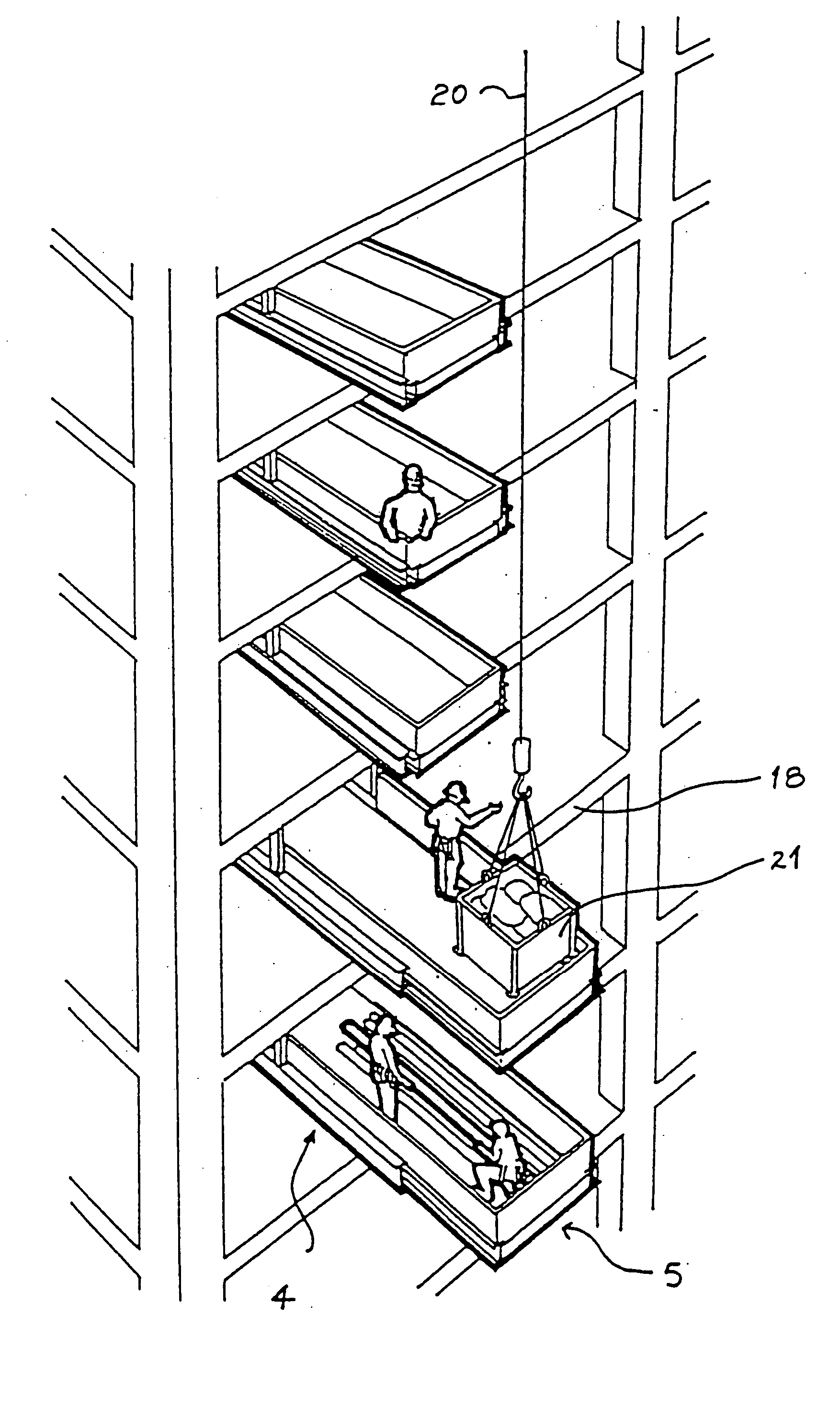
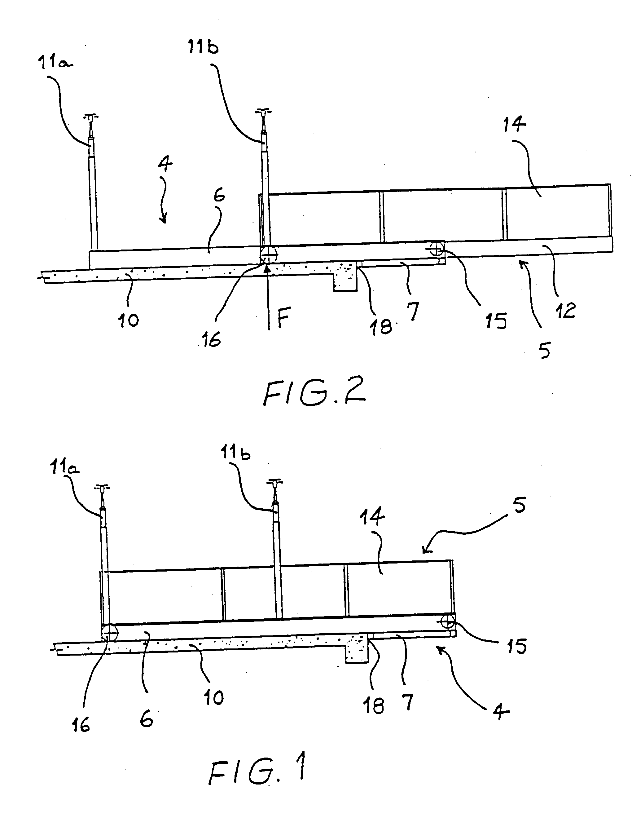
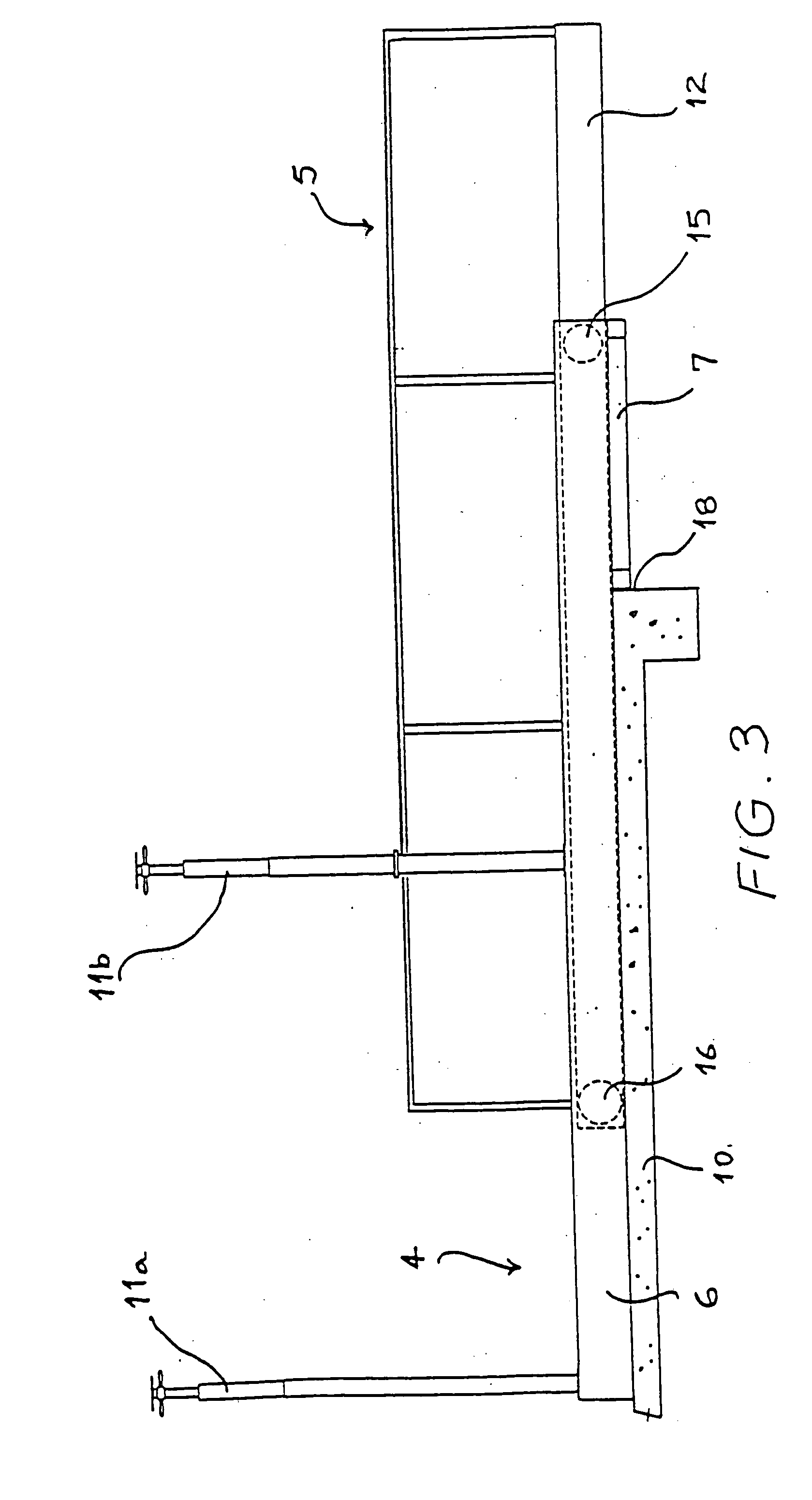
[0028] The first and second embodiments of the platforms shown in FIGS. 1 to 4 each comprise a stationary support structure 4, and a movable deck portion 5 adapted to move between a retracted configuration and an in-use extended configuration. The only difference between the two embodiments is that the movable deck 5 of the first embodiment extends to a further extent than that of the movable deck in the second embodiment. The first and second embodiments have similar components, and like reference numerals are use for both embodiments.

[0029] In each embodiment, a stationary support structure 4 comprises two, spaced apart, substantially parallel, rolled steel joists (guide beams) 6. Those joists may be channel sectioned, but preferably are conventional I beams, comprising a central upright web and substantially horizontal, upper and lower flanges. The joists 6 are united into a base frame for the stationary portion 4 by at least a cross member (not shown) extending from one to the o...


PUM


Abstract

A construction platform comprising a stationary support structure adapted to be fixedly secured to the floor of a building under construction and project from the edge of the building to a predetermined maximum extent, and a movable deck mounted on the stationary structure which may be extended as a cantilever therefrom or retracted into at least substantial registration therewith.

Description

[0001] This invention relates to so called construction platforms. That is to say to temporary loading platforms, which, in use, project from the above ground floors of multi-storey buildings under construction, to act as landings for the receipt of loads of building material and the like deposited on the platform by a crane.[0002] Construction platforms are widely used in the construction of reinforced concrete or steel framed buildings wherein the outer skin of the building is not load bearing, and is not put in place until after the main supporting structure of the building has been finished, and its major internal fittings have been installed.[0003] Such construction platforms customarily comprise an inboard portion, which rests upon and is fixed to an edge margin of a building floor, and an outboard portion, including a landing deck, which extends as a cantilever from the inboard portion beyond the edge of the floor. Conveniently, the inboard portion may comprise a base frame a...

Claims


Application Information

Patent Timeline
Patent Type & Authority Applications(United States)
IPC IPC(8): E04G3/18E04G3/00E04G3/28E04G21/18
CPCE04G3/18E04G3/28E04G21/166E04G21/14E04G2003/283
Inventor PRESTON, JOHN CLEMENT
Owner MEVON PTY
Why Eureka
Try Eureka