Foot type stand column and short cantilever five-axis linkage machine tool

A five-axis linkage machine tool and column technology, applied in the field of machine tools, can solve the problems of large swing radius of the double-degree-of-freedom rotary table, difficulty in obtaining cutting speed, and large swing error, etc., to improve cutting speed and surface finish, and shorten the cantilever The effect of compact length and size

Active Publication Date: 2014-11-26
NANJING GEWAI TRACK TRAFFIC EQUIP CO LTD
View PDF9 Cites 1 Cited by
  • Summary
  • Abstract
  • Description
  • Claims
  • Application Information

AI Technical Summary

Problems solved by technology

[0005] Hybrid five-axis linkage machine tools also have some shortcomings. For example, the gantry type hybrid five-axis linkage machine tool with application number 200810196596.1 has a large swing radius of the two-degree-of-freedom rotary table around the fixed axis, and there are swing errors caused by manufacturing errors. Too large deficiency; the application number is 200810196595.7 for the hybrid machine tool with parallel cutter heads. Although the machine tool has high rigidity, the cutting motion of the tool must be realized by a pair of bevel gears. Due to the limitation of the characteristics of bevel gear transmission, it is difficult to obtain 10,000 rpm Cutting speed above
[0006] In short, the existing five-axis linkage machine tool structure, when processing metal parts with a large length / width ratio, has insufficient performance in terms of machine stiffness, machining accuracy, work space, cutting speed, and manufacturing cost.

Method used


Image

  • Foot type stand column and short cantilever five-axis linkage machine tool
  • Foot type stand column and short cantilever five-axis linkage machine tool
  • Foot type stand column and short cantilever five-axis linkage machine tool

Examples


Embodiment Construction

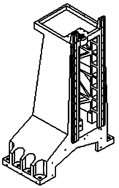
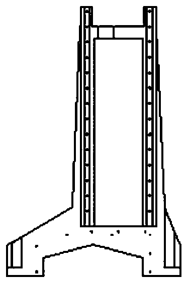
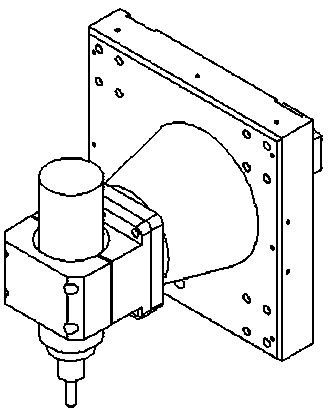
[0028] As shown in Figure 1-3, a five-axis linkage machine tool with a foot-shaped column and a short cantilever includes a machine base 1, an X-axis moving motor 10, a Y-axis moving motor 2, a Z-axis linear moving motor 4, a cross slide, a rotary Workbench 6, swing motor 102, electric spindle 106 and foot-shaped column 3.

[0029] A cross slide is arranged on the machine tool base 1, X and Y-axis carriages are installed on the cross slide, a rotary table 6 is installed on the Y-axis carriage, and a workpiece 5 is installed on the rotary table 6.

[0030] The foot-shaped column 3 is arranged on the base of the machine tool and is located on one side of the cross slide table. The foot-shaped column 3 includes a vertical section and a mounting seat. The lower end of the vertical section is arranged at one end of the mounting seat. A shaft movement channel is provided with a V-shaped through hole in the middle of the width direction of the mounting seat.

[0031] The top of the ...


PUM


Abstract

A foot type stand column and short cantilever five-axis linkage machine tool comprises a base of the machine tool, an X-axis linear movement motor, a Y-axis linear movement motor, a Z-axis linear movement motor, a cross-shaped sliding table, a rotating table, a swing motor, an electric main shaft and a foot type stand column. The foot type stand column is arranged on the base of the machine tool and located on one side of the cross-shaped sliding table, the foot type stand column comprises a vertical section and an installing base, the lower end of the vertical section is arranged at one end of the installing base, the middle of the vertical section in the height direction is of a hollow structure and forms a Z-axis movement channel, and a V-shaped through hole is formed in the middle of the installing base in the width direction; the Z-axis linear movement motor is arranged at the top of the vertical section of the foot type stand column, a speed reducer is installed at the front end of a Z-axis drag plate and connected with the swing motor through a coupler, the electric main shaft is installed at the output end of the speed reducer, the Y-axis movement motor is installed on the base of the machine tool and located in the V-shaped through hole in the installing base of the foot type stand column, and the X-axis movement motor is arranged on the upper surface of the crossed-shaped sliding table. The machine tool is mainly used for machining large parts large in height, high in rigidity and suitable for machining hard materials.

Description

technical field [0001] The invention relates to a machine tool, in particular to a vertical five-axis linkage machine tool. Background technique [0002] The five-axis linkage machine tool is an effective equipment for processing complex curved surfaces in space. Since the five-axis linkage machine tool has 5 motion axes, compared with the 3-axis machining center, the rigidity is low and the error accumulation is large; in order to overcome the defect of insufficient rigidity, the domestic Many five-axis linkage configurations have been designed outside, and these five-axis linkage configurations can be divided into three types: parallel connection, hybrid connection and series connection according to the structure type. [0003] Parallel five-axis linkage machine tools currently have the disadvantage of small machining space / machine tool size ratio; and the ball joints of the rods are difficult to process, resulting in shortcomings such as low rigidity and small rotation an...

Claims


Application Information

Patent Timeline
Patent Type & Authority Applications(China)
IPC IPC(8): B23Q1/01B23Q1/26B23Q5/40
CPCB23Q1/017B23Q1/522B23Q1/625B23Q1/626B23Q5/40
Inventor 姜铭姜欣悦朱望东孙钊
Owner NANJING GEWAI TRACK TRAFFIC EQUIP CO LTD
Why Eureka
Try Eureka