

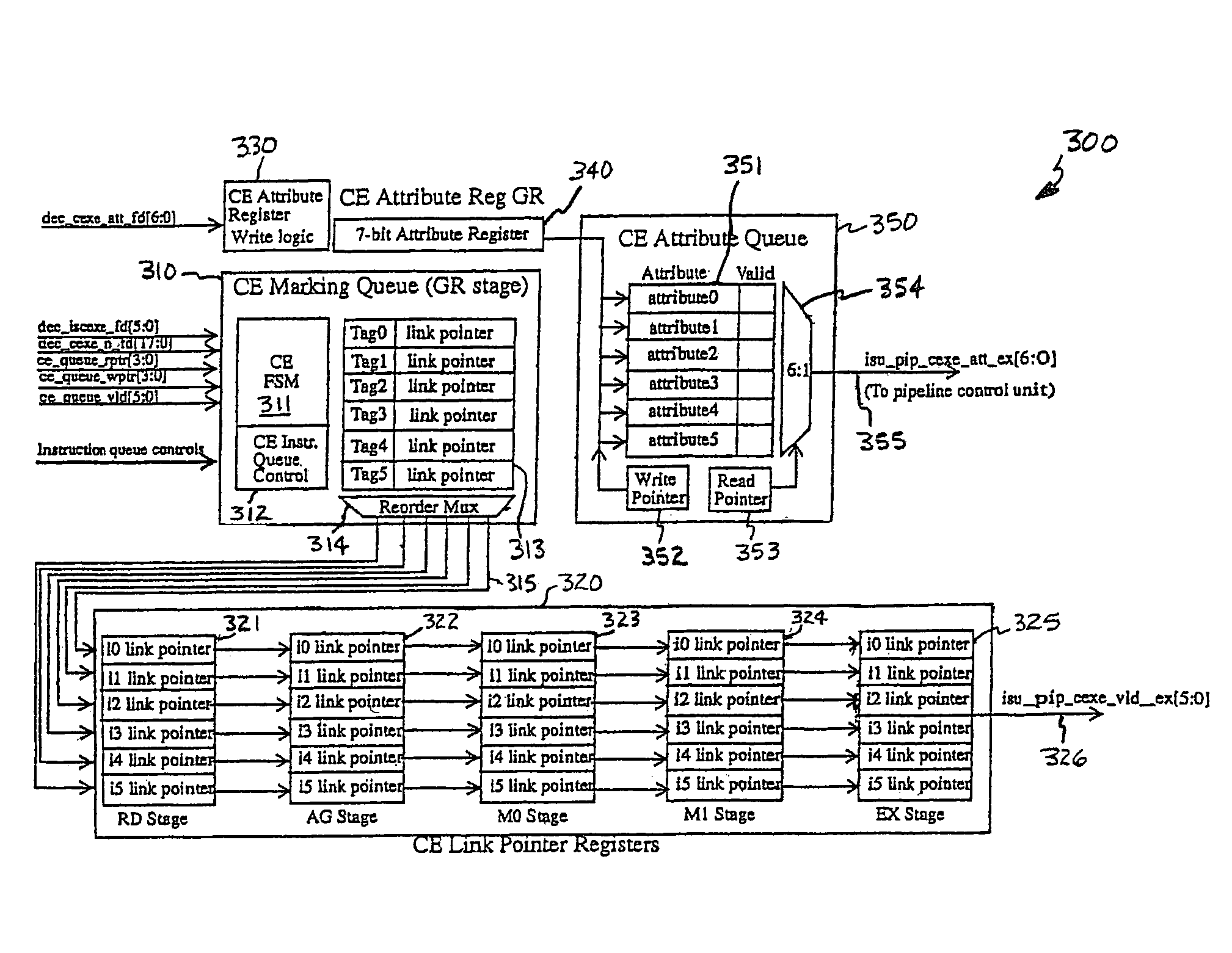
Conditional link pointer register sets marking the beginning and end of a conditional instruction block where each set corresponds to a single stage of a pipeline that moves link pointers through each corresponding register of said register sets as instructions move through the pipeline
a register set and conditional instruction technology, applied in the field of digital signal processors, can solve the problems of high circuit temperature, increased power consumption and temperature of dsp, and damage to dsp,
- Summary
- Abstract
- Description
- Claims
- Application Information
AI Technical Summary
Benefits of technology
Problems solved by technology
Method used
Image

Examples
Embodiment Construction
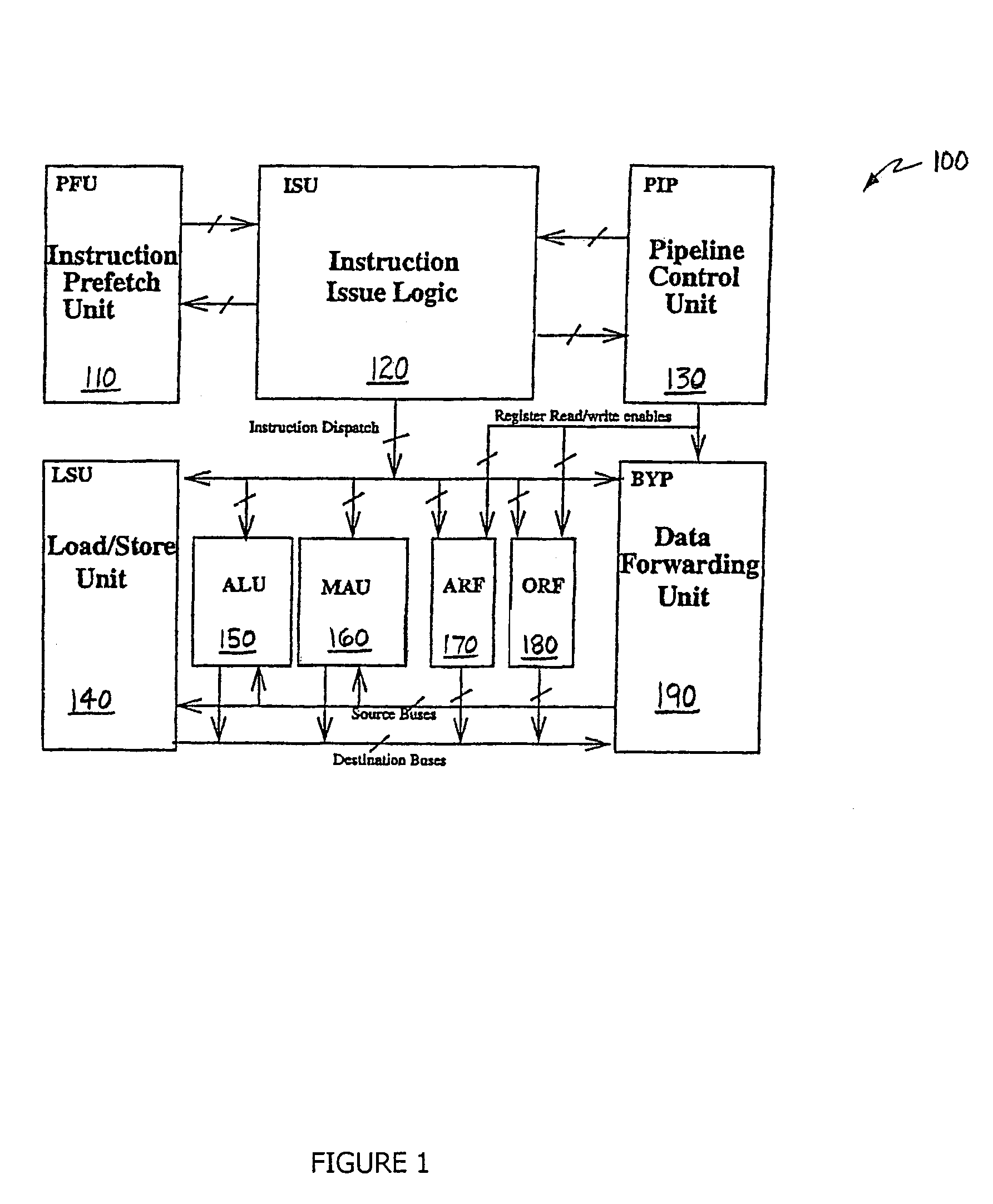
[0026]Referring initially to FIG. 1, illustrated is an exemplary DSP, generally designated 100, which may form an environment within which a mechanism for conditionally executing instructions constructed according to the principles of the present invention can operate. Those skilled in the pertinent art should understand that the mechanism of the present invention may be applied to advantage in other conventional or later-discovered DSP or general-purpose, non-DSP, processor architectures.
[0027]The DSP 100 contains an instruction prefetch unit (PFU) 110. The PFU 110 is responsible for anticipating (sometimes guessing) and prefetching from memory the instructions that the DSP 100 will need to execute in the future. The PFU 110 allows the DSP 100 to operate faster, because fetching instructions from memory involves some delay. If the fetching can be done ahead of time and while the DSP 100 is executing other instructions, that delay does not prejudice the speed of the DSP 100.
[0028]Th...
PUM
 Abstract
Description
Claims
Application Information