Apparatus for cleaning and drying substrates

a technology for drying substrates and apparatuses, which is applied in the direction of cleaning processes and apparatus, cleaning apparatus and processes, chemistry apparatus and processes, etc. it can solve the problems of subsequent device failure, spotting, and residues left on the surface of the substrate, and achieves the speed of marangoni drying, reduce fluid consumption, and increase the surface tension gradient

Inactive Publication Date: 2007-08-07
APPLIED MATERIALS INC
View PDF29 Cites 29 Cited by
  • Summary
  • Abstract
  • Description
  • Claims
  • Application Information

AI Technical Summary

Benefits of technology

[0010]a second linear nozzle positioned proximate the first nozzle such that drying vapors therefrom affect the fluid sprayed from the first linear nozzle to create a Marangoni drying effect;
[0014]The active supply of drying vapors via drying vapor nozzles provides tight control over the concentration of drying vapors at the drying meniscus. Unlike other bath-type Marangoni dryers, the present invention provides a continuous supply of fresh rinsing fluid which, unlike the more stagnant bath fluids, has no drying vapors mixed therewith. Thus, the present invention experiences a larger surface tension gradient between the drying meniscus and the remainder of the rinsing fluid flow. The larger surface tension gradient enhances the speed of Marangoni drying. Most significantly, because less fluid is required to spray the entire surface of a substrate than to submerge the substrate, the use of rinsing fluid nozzles significantly reduces fluid consumption as compared to conventional bath-type Marangoni dryers.
[0015]In a most preferred embodiment, the throughput of the inventive cleaning / drying system is enhanced via a two-part tank, having a first portion for receiving and cleaning a substrate and a second portion for rinsing a substrate. The first and the second portion of the cleaning tank are in fluid communication. A drying enclosure which encloses the rinsing fluid source and the drying vapor source is operatively coupled above the second portion of the tank, for receiving substrates therefrom.
[0016]Preferably, a shuttle which supports a substrate along the outer edges thereof, receives a first substrate in the first portion of the tank and transports the substrate to the second portion of the tank. Thereafter, the lifting mechanism lifts the first substrate into the drying enclosure, and the shuttle returns to the first portion of the tank. In this manner, the first substrate may be dried within the drying enclosure as a second substrate is loaded into the first portion of the cleaning tank, thus providing greater throughput and a corresponding decrease in processing costs.

Problems solved by technology

After removal from the rinsing bath, absent use of a drying apparatus, the bath fluid would evaporate from the substrate's surface causing streaking, spotting and / or leaving bath residue on the surface of the substrate.
Such streaking, spotting and residue can cause subsequent device failure.
Although apparatuses such as that disclosed in the '536 Application effectively remove fluid from the substrate, they consume a considerable amount of fluid because the bath fluid cannot be filtered and recirculated to remove drying vapor therefrom.
Further, considerable time is required to transfer a substrate from the cleaning to the rinsing bath, or to replace bath fluid.

Method used


Image

  • Apparatus for cleaning and drying substrates
  • Apparatus for cleaning and drying substrates
  • Apparatus for cleaning and drying substrates

Examples


Embodiment Construction

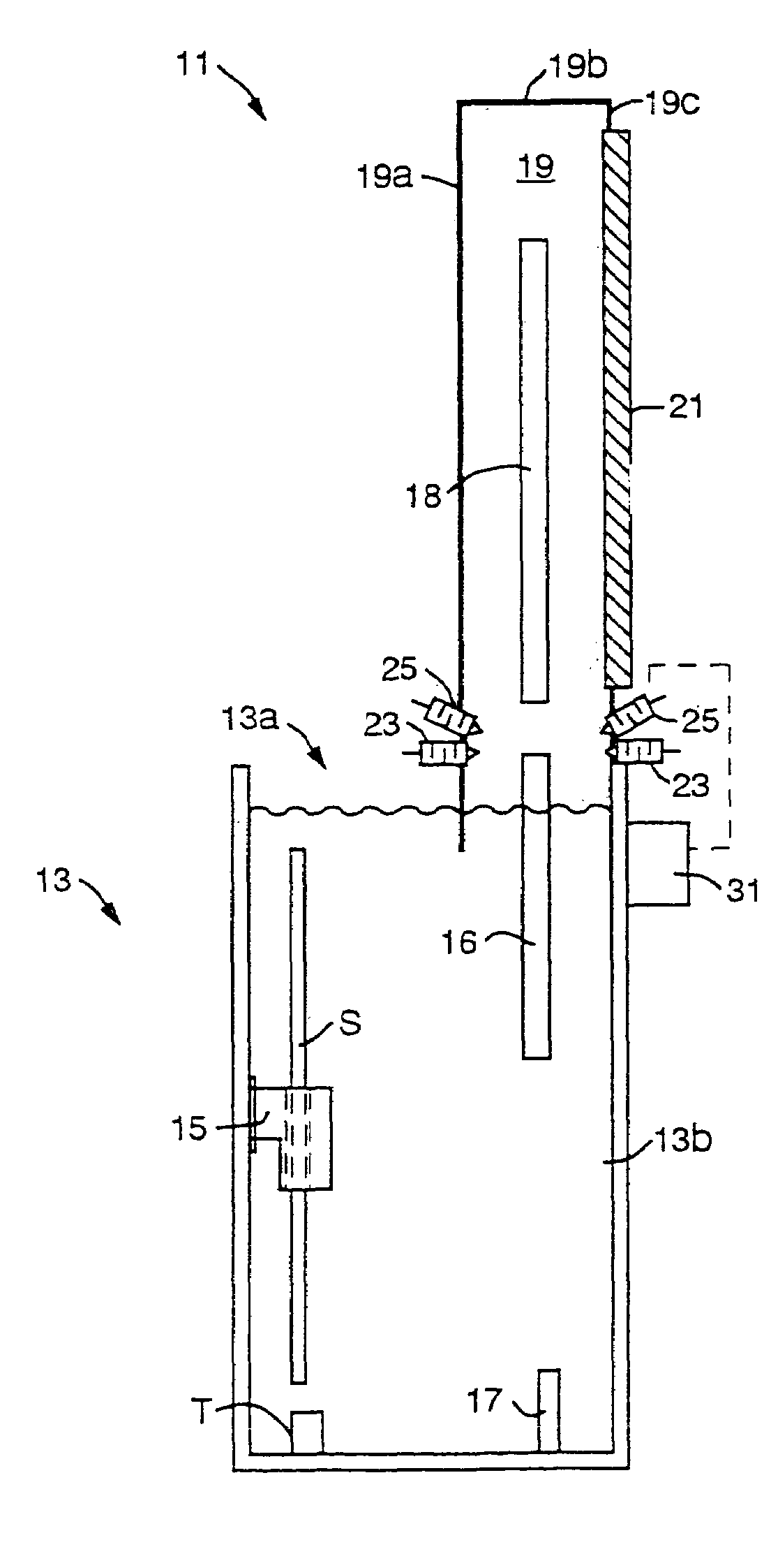
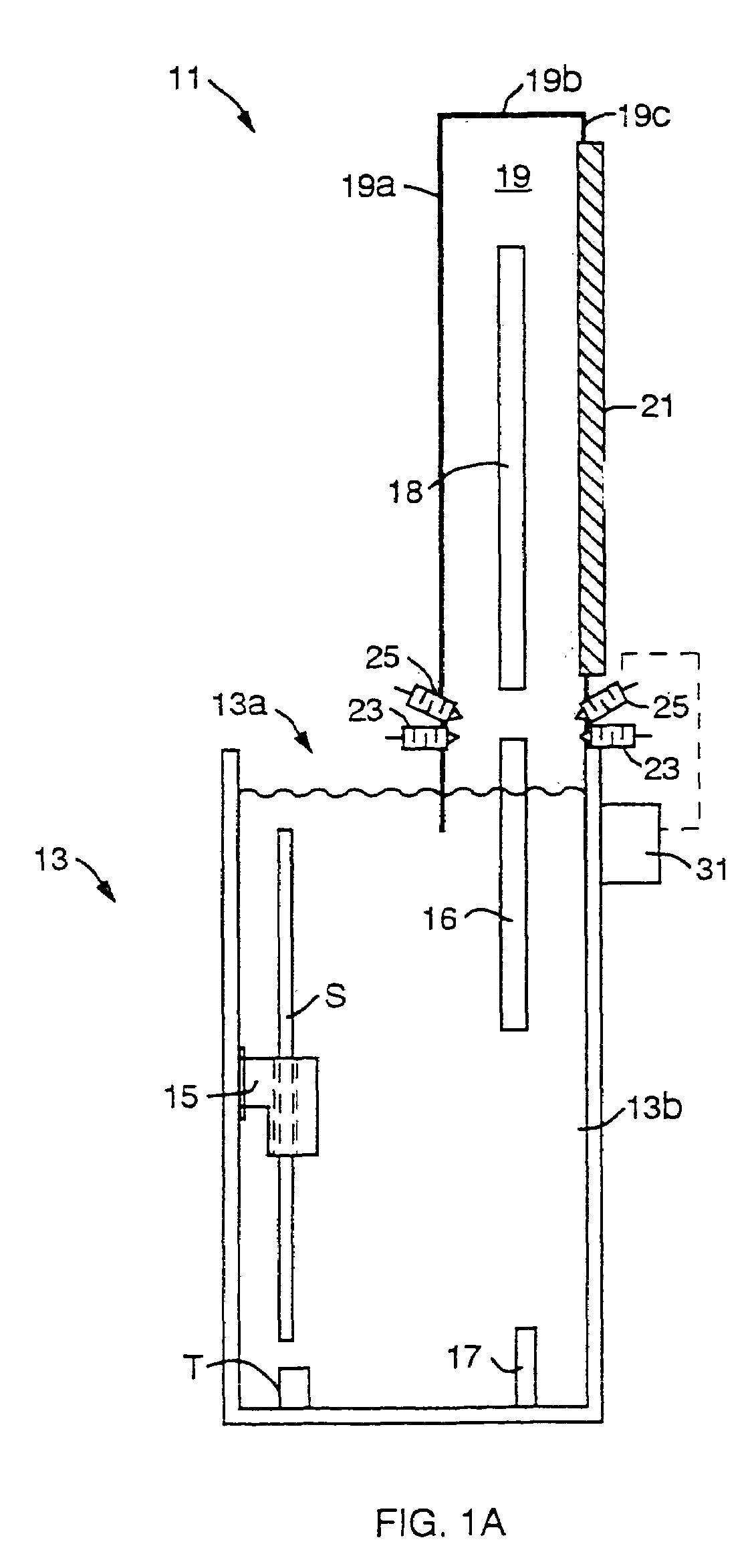
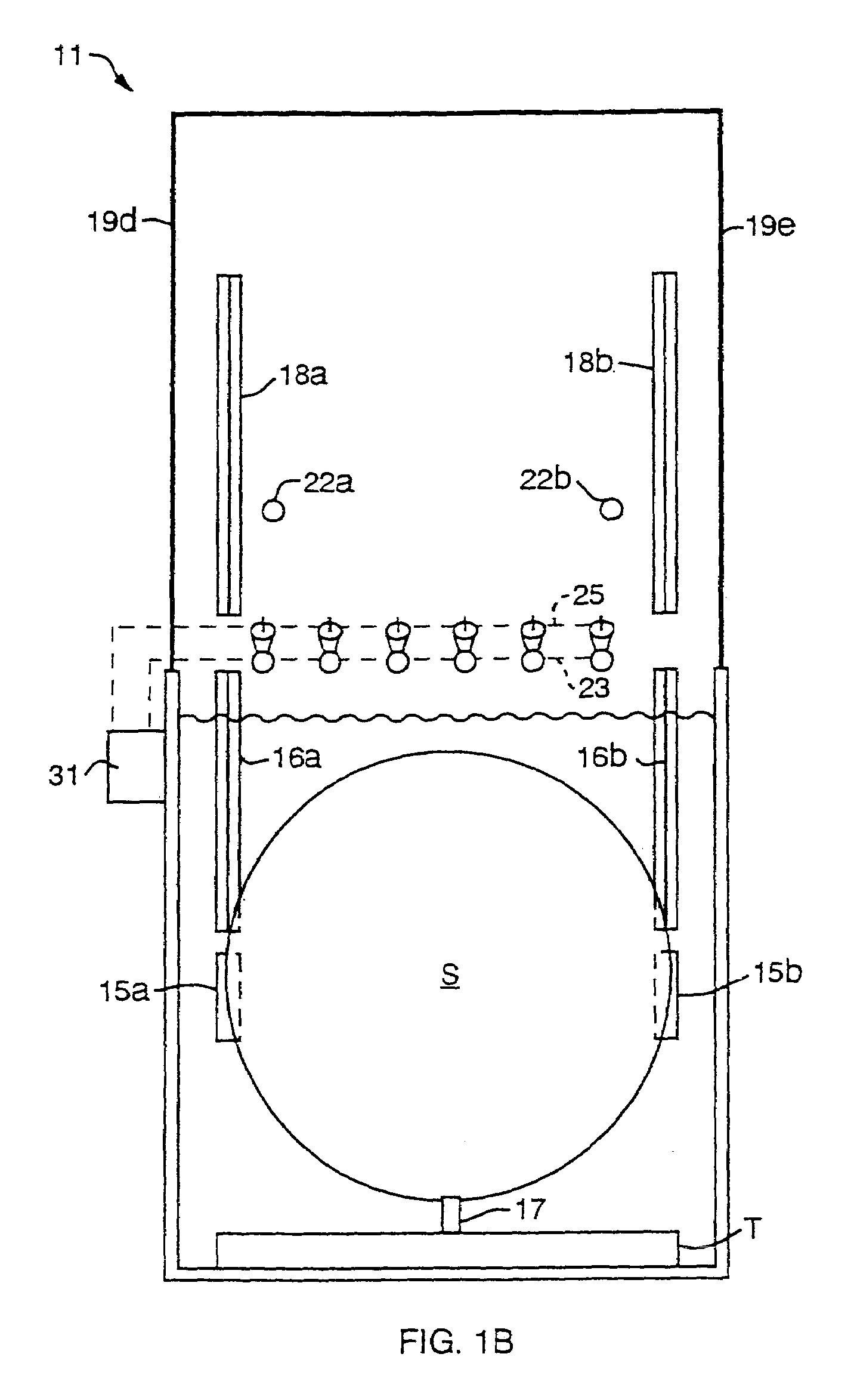
[0022]FIGS. 1A and 1B are a side elevational view and a front elevational view, respectively, of a preferred cleaning / drying system 11 configured in accordance with the present invention. The preferred cleaning / drying system 11 comprises a tank 13 of cleaning fluid. The tank 13 comprises two portions, a substrate receiving and cleaning portion 13a and a substrate rinsing portion 13b. A substrate shuttle 15 is operatively coupled to carry a substrate S from the substrate receiving and cleaning portion 13a to the substrate rinsing portion 13b. The substrate shuttle 15 preferably is designed to support the substrate S vertically along the lateral sides thereof as shown in FIG. 1B. Thus, a lifting mechanism 17 within the substrate rinsing portion 13b of the tank 13 can extend upward between a first and a second supporting sides 15a, 15b of the substrate shuttle 15, lifting the substrate S therebetween.

[0023]A first pair of rails 16a, 16b are permanently mounted within the rinsing portio...


PUM


Abstract

A method and apparatus for cleaning, rinsing and Marangoni drying substrates is provided. A line of fluid is sprayed along a substrate surface forming an air / fluid interface line, and a line of drying vapor is supplied to the interface line to achieve Marangoni drying. Thus, a large portion of the substrate is simultaneously dried. A preferred apparatus employs a tank of cleaning and / or rinsing fluid. Above the tank fluid a source of rinsing fluid directs rinsing fluid to the surface of a substrate forming a meniscus on the substrate surface as the substrate is lifted from the cleaning fluid, and a drying vapor source directs drying vapor to the meniscus. The drying vapor lowers the surface tension of the meniscus, inducing a Marangoni flow of rinsing fluid from the substrate's surface, and thereby drying the substrate. The cleaning fluid tank has a substrate receiving and cleaning portion and a substrate rinsing portion. The rinsing fluid source and the drying vapor source are enclosed by a drying enclosure above the rinsing portion of the tank. Thus, substrate loading, cleaning, rinsing, drying and unloading are performed with at least partial overlap in time.

Description

[0001]This application is a division of U.S. patent application Ser. No. 10 / 046,423, filed Oct. 25, 2001 now U.S. Pat. No. 6,746,544, which is a continuation of U.S. patent application Ser. No. 09 / 280,118, filed Mar. 26, 1999 now U.S. Pat. No. 6,328,814 both of these patent applications are hereby incorporated by reference herein in their entirety.FIELD OF THE INVENTION[0002]The present invention relates to processes for simultaneously rinsing and drying substrates. More particularly, the present invention relates to an ultra clean process and apparatus for simultaneously rinsing and Marangoni drying a semiconductor substrate.BACKGROUND OF THE INVENTION[0003]As semiconductor device geometries continue to decrease, the importance of ultra clean processing increases. Aqueous cleaning within a tank of fluid (or a bath) followed by a rinsing bath (e.g., within a separate tank, or by replacing the cleaning tank fluid) achieves desirable cleaning levels. After removal from the rinsing bat...

Claims


Application Information

Patent Timeline
Patent Type & Authority Patents(United States)
IPC IPC(8): B08B7/04B08B3/04B08B3/10B08B3/12H01L21/00H01L21/304
CPCH01L21/67028Y10S134/902
Inventor FISHKIN, BORISSHERRARD, MICHAEL
Owner APPLIED MATERIALS INC
Why Eureka
Try Eureka