Volatile dispenser with oriented fibrous emanator

a dispenser and fibrous material technology, applied in the field of volatile dispensers, can solve the problems of clogging, significant problems using these mixtures, and the tendency of carrier fluids to evaporate sooner, and achieve the effect of enhancing the linear vaporization of the contained volatile liquid and reducing clogging

Active Publication Date: 2007-08-07
SC JOHNSON & SON INC
View PDF29 Cites 20 Cited by
  • Summary
  • Abstract
  • Description
  • Claims
  • Application Information

AI Technical Summary

Benefits of technology

[0016]The present invention substantially overcomes the problem of emanator clogging. By reducing clogging it also enhances linear vaporization of its contained volatile liquid.
[0018]When the vapor pressures of the individual components are at least 0.008 mm Hg, the inventor discovered that the selective evaporation of individual components is significantly reduced.
[0019]Emanators with fine capillary passages can be used to vaporize a volatile fluid in which most of the components have a vapor pressure of no less than 0.008 mm Hg and a low viscosity. Emanators with fine internal capillaries can be fashioned quite thin and broad, with a high surface area to volume ratio, without running the risk of plugged passageways and a blocked emanator.
[0020]The present invention also overcomes the need for a large emanator, since the lack of clogging and the effective fluid transport to the surface using the disclosed bonded fiber emanator provides a large effective surface area over the entire several week life of a typically disposable volatile dispenser.

Problems solved by technology

For many consumers it is irritating when a volatile scent dispenser provides an overwhelming scent for the first few hours or days, then rapidly fades away to the merest suggestion of the original scent.
There are significant problems using these mixtures.
The problems arise because the mixtures are just that—mixtures—and do not stay perfectly mixed as they evaporate.
While they do help carry the dispensed liquid up the wick, the carrier fluids tend to evaporate sooner.
As a result, they leave significant amounts of the dispensed liquid within the wick itself and significant deposits on the end of the wick.
This reduces the transport of both the carrier and the dispensed liquid and eventually causes the liquid transport up the wick to cease altogether.
In sum, while the carriers can assist the transport of dispensed liquid, they still do not provide the linearity of dispensing that is desired.

Method used


Image

  • Volatile dispenser with oriented fibrous emanator
  • Volatile dispenser with oriented fibrous emanator
  • Volatile dispenser with oriented fibrous emanator

Examples


Embodiment Construction

[0037]While the present invention is susceptible of being made in any of several different forms, the drawings show a particularly preferred form of the invention. One should understand, however, that this is just one of many ways the invention can be made. Nor should any particular feature of the illustrated embodiment be considered a part of the invention, unless that feature is explicitly mentioned in the claims. In the drawings, like reference numerals refer to like parts throughout the several views.

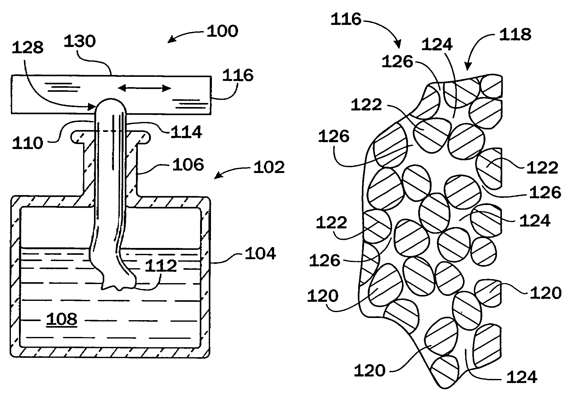
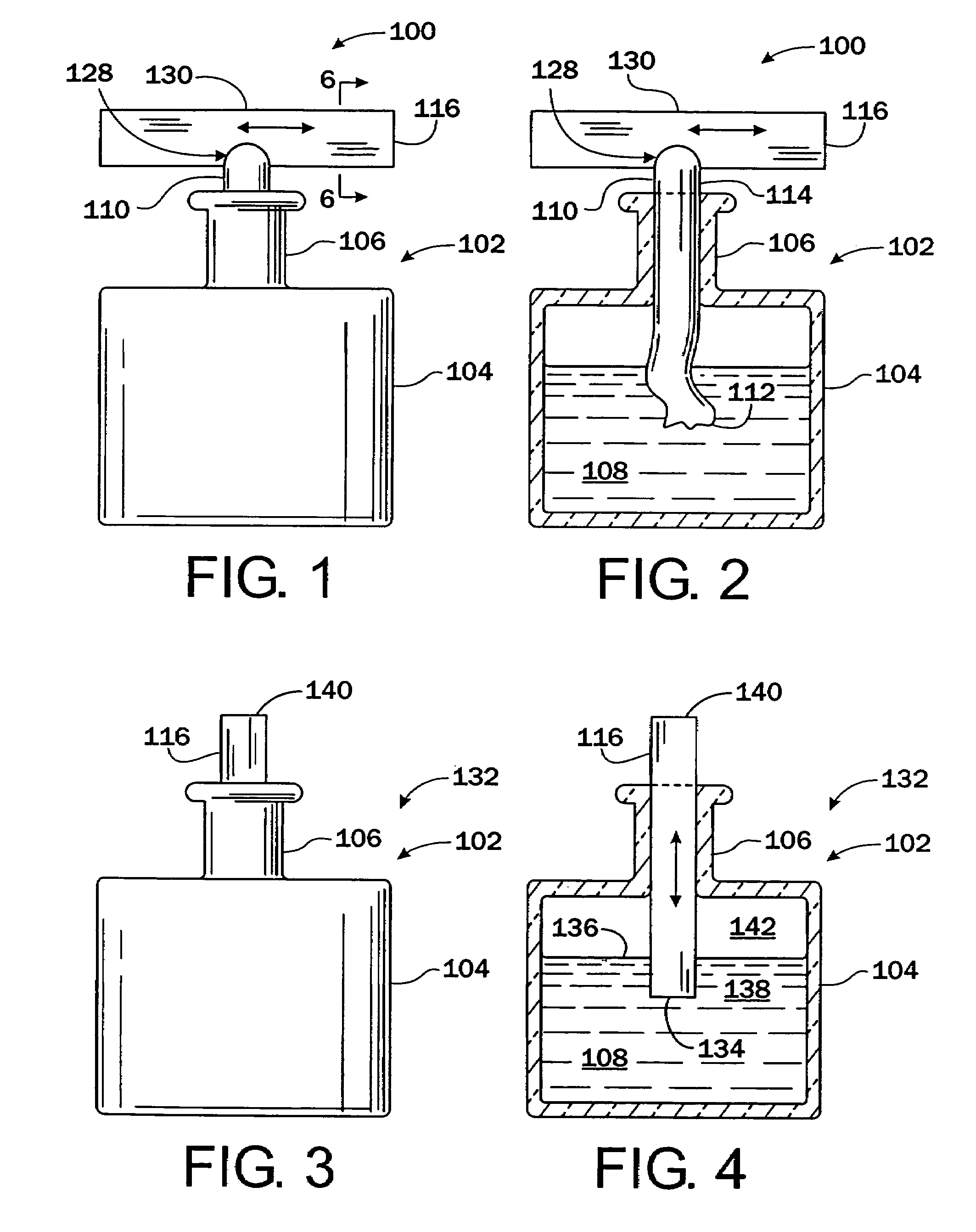
[0038]FIGS. 1 and 2 show a volatile dispenser 100. It includes a reservoir 102 having a generally cylindrical body 104 and a narrow neck 106. Reservoir 102 contains a volatile liquid 108.

[0039]A wick 110 has a lower end 112 that is disposed in the liquid 108, and an upper end 114 that extends out of reservoir 102 through neck 106. Upper end 114 is exposed to the surrounding atmosphere.

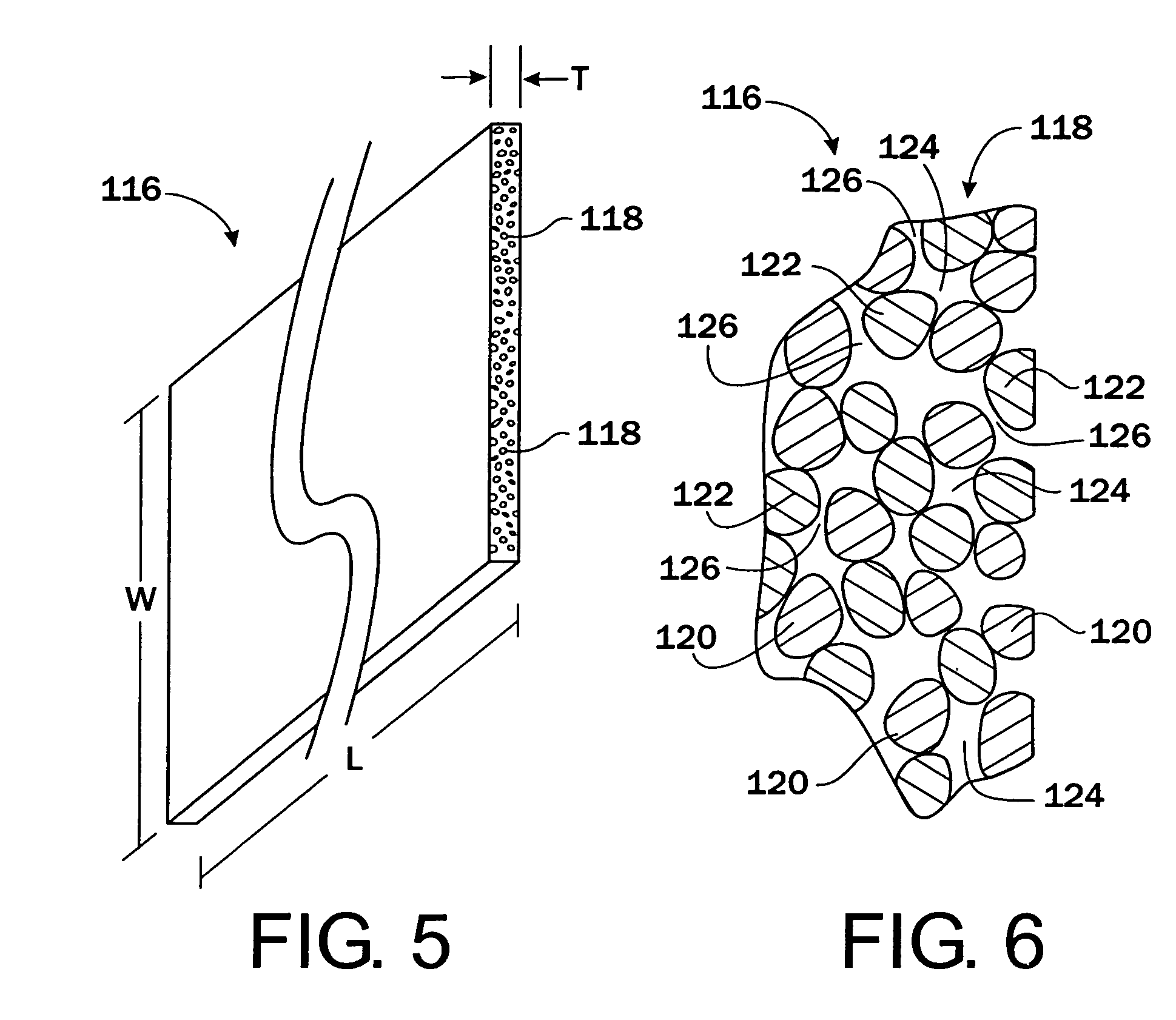
[0040]An emanator 116 abuts and is in fluid communication with end 114 of wick 110. Referring to FI...


PUM

PropertyMeasurementUnit
viscosityaaaaaaaaaa
viscosityaaaaaaaaaa
vapor pressuresaaaaaaaaaa

Abstract

A volatile dispenser is provided, including a reservoir containing a quantity of volatile liquid having a viscosity of no greater than 3.9 centipoises. Each of its individual components has a vapor pressure of no less than 0.008 mm Hg. The dispenser also includes an emanator fluidly coupled to the reservoir (either directly or through a wick) that is comprised of elongated oriented bonded fibers, the fibers being impermeable to the volatile material.

Description

FIELD OF THE INVENTION[0001]The present invention generally relates to volatile dispensers. More particularly, it relates to liquid volatile dispensers having bonded fibrous emanators.BACKGROUND OF THE INVENTION[0002]A common system for dispensing volatile materials such as perfumes or fragrances includes an impermeable reservoir containing a liquid mixture of the volatile materials. This reservoir has a narrow opening that supports a wick. The wick is inserted through the opening in the reservoir until one end of the wick contacts the liquid in the reservoir and the other end extends outside the reservoir into the surrounding atmosphere.[0003]In operation, the liquid is absorbed by the fibers of the wick and is drawn upward through the wick fibers by microscopic capillary action. The liquid passes up the wick, through the wick opening in the reservoir and wets that portion of the wick that is outside the reservoir.[0004]Since the surrounding atmosphere has a lower partial pressure ...

Claims


Application Information

Patent Timeline
Patent Type & Authority Patents(United States)
IPC IPC(8): A61L9/04A61L9/12A01M1/20A61L9/03
CPCA01M1/2044A61L9/037A61L9/127
Inventor MARTENS, III, EDWARD J.
Owner SC JOHNSON & SON INC
Why Eureka
Try Eureka