Security bench

a technology for security benches and benches, applied in the direction of auditorium chairs, ways, constructions, etc., can solve the problems of unattractive and unpleasant aesthetics, urban blight, and inability to meet the needs of people,

Inactive Publication Date: 2007-08-07
WALTON DOROTHY GOODRICH
View PDF85 Cites 23 Cited by
  • Summary
  • Abstract
  • Description
  • Claims
  • Application Information

AI Technical Summary

Benefits of technology

[0013]According to alternative embodiments, the security street bench support base may have a hollow interior, for filling with ballast at the installation location. In this manner, much of the weight/mass of the bench can be eliminated for manufacturing and shipping, and then added to the bench on site using common, inexpensive/free materials such as rock, concrete chunks, sa

Problems solved by technology

After the bombing of the Alfred P. Murrah Federal Building in Oklahoma City, and even more so after the events of Sep. 11, 2001; however, such barriers were put in place around most key government buildings, e.g., the White House area and federal courthouses.
While conventional concrete barricades work fairly well, they are completely functional in nature and, as such, quite unattractive and unpleasing from an aesthetic sense.
In fact, pu

Method used


Image

  • Security bench
  • Security bench
  • Security bench

Examples


first embodiment

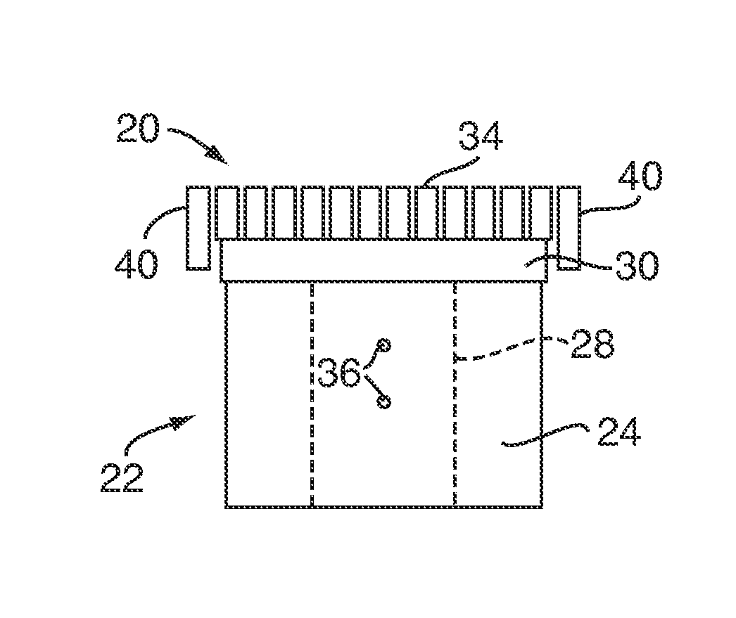
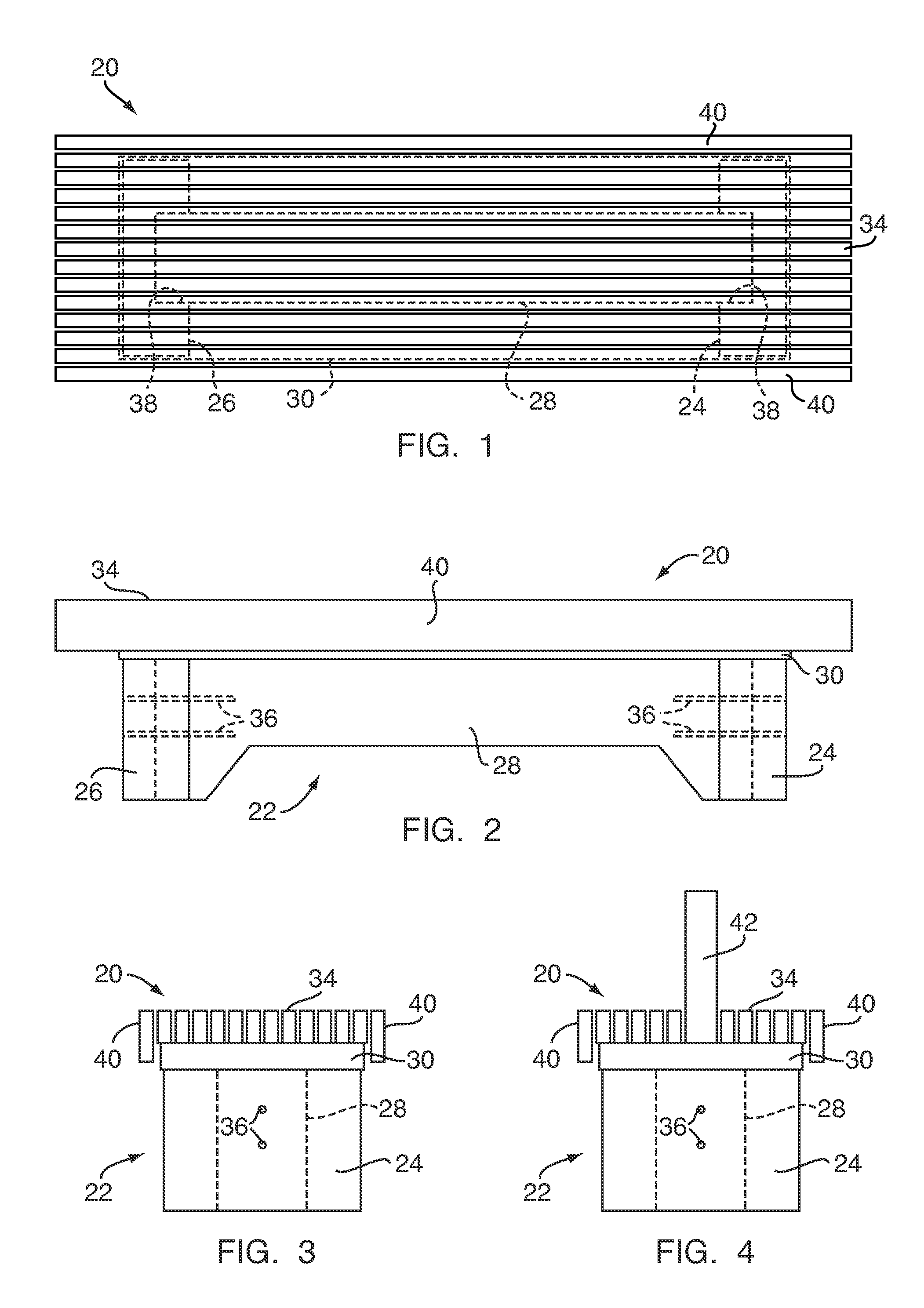
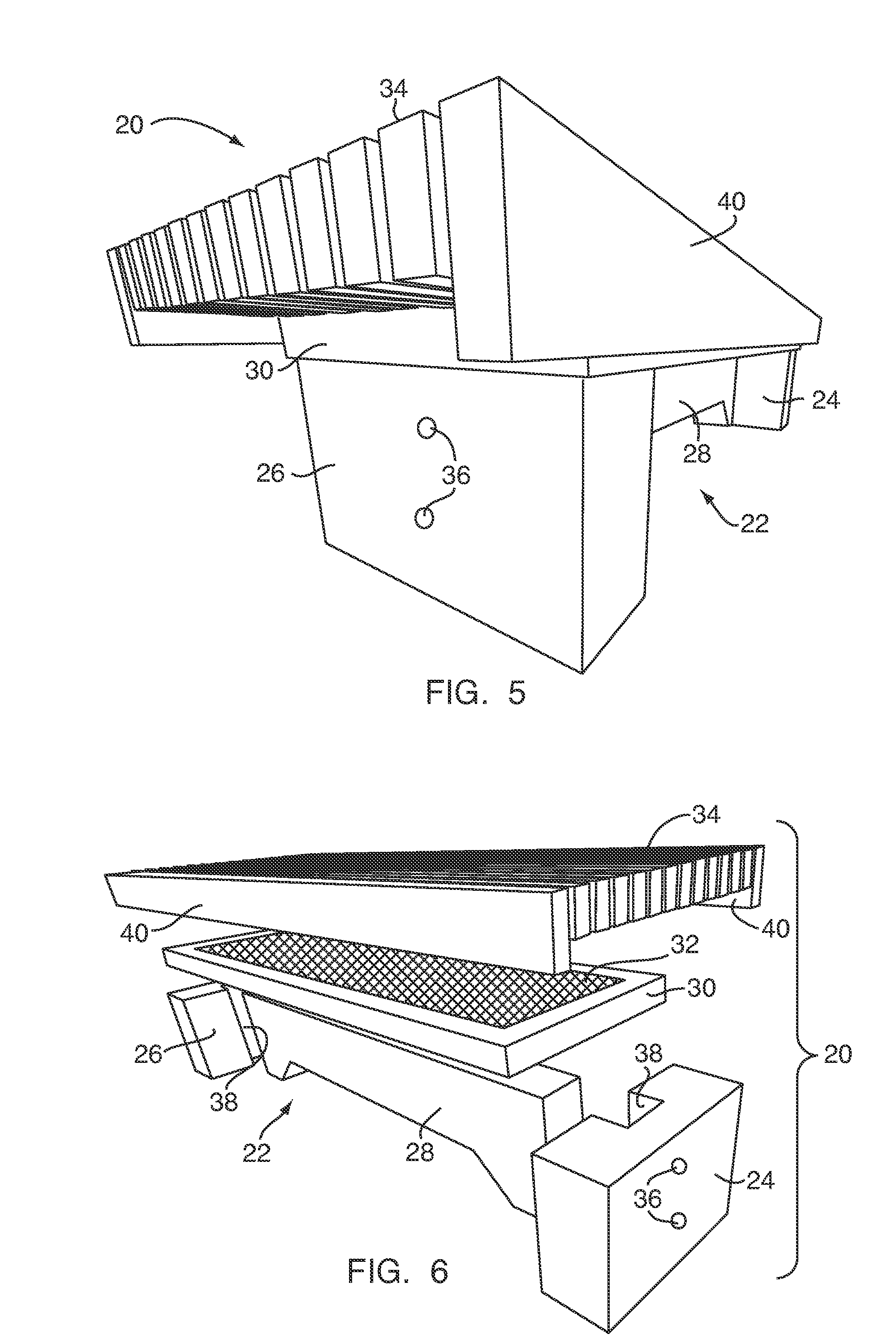
[0038]With reference to FIGS. 1-6, a security bench 20 comprises: a high-mass, generally I-shaped base 22 having two end supports 24, 26 and a transverse section 28; a structural steel frame 30; a “security screen”32 (a panel of wire mesh or screening); and a seating surface 34. As best shown in FIG. 2, the end supports 24, 26 are attached to the transverse section 28 by a plurality of bolts 36. The bolts 36 extend through the end supports 24, 26 and into the transverse section 28 to a depth consistent with the demands of structural integrity and the desired capability of the piece to act as shield or barricade. The security screen 32, placed under the seating surface 34 and not obvious to public view, is attached integrally to the steel frame 30, which is in turn attached to the end supports 24, 26 by means of standard high-strength bolts or other fixtures (not shown). Finally, the seating surface 34 is attached to the frame 30 and / or base 22 using standard connectors.

[0039]The bas...

second embodiment

[0056]FIGS. 7-11 show the present invention. Here, a security street bench 50 with a greater degree of “hardening” is generally similar to the bench 20, but includes a wider and more massive transverse portion 52. As such, instead of having a relatively narrow, slightly arched transverse 28, the transverse portion 52 of the bench 50 is significantly wider, forming a large, generally rectangular solid with generally square ends. To accommodate this increased width, the end supports 54, 56 have wider vertical slots 58. This design, with the larger, more substantial transverse portion 52, would provide a greater degree of defense against explosive debris and other considerations such as limiting vehicle access.

[0057]The above-noted designs may be modified to change the manner or degree in which possible debris or explosive force is focused, deflected, or repelled. For example, an additional embodiment of the present invention is shown in FIGS. 12-16. There, a bench 70 is generally simi...


PUM


Abstract

A security bench for use as a seat and as a defensive barricade against vehicles and explosive force comprises a support base, a framed screen securely attached to and overlapping the top of the base, and a seating surface attached to the top of the framed screen. The base, made of granite, concrete, or the like, is relatively massive, providing resistance to vehicular and explosive force. The frame portion of the framed screen, made from structural steel, reinforces the structural integrity of the base, and, along with the screen (and potentially the seating surface) acts to repel or absorb explosive force or debris.

Description

[0001]This application claims priority from a Provisional Application Ser. No. 60 / 524,711, filed Nov. 24, 2003, and from a Provisional Application Ser. No. 60 / 567,572, filed May 4, 2004, both hereby incorporated by reference in their entireties.FIELD OF THE INVENTION[0002]The present invention relates to barricades, closures, and furniture items, and, more particularly, to furniture items that provide both furniture / seating functionality and defensive barricade functionality.BACKGROUND OF THE INVENTION[0003]Squat, wall-like, concrete traffic barricades have long been used for temporarily dividing road lanes and cordoning off construction areas. After the bombing of the Alfred P. Murrah Federal Building in Oklahoma City, and even more so after the events of Sep. 11, 2001; however, such barriers were put in place around most key government buildings, e.g., the White House area and federal courthouses. This was done to prevent vehicles from being easily parked in close proximity to bui...

Claims


Application Information

Patent Timeline
IPC IPC(8): A47C15/00A47C1/12E01F15/00
CPCA47C11/00E01F13/12
Inventor WALTON, TOBY EVANS
Owner WALTON DOROTHY GOODRICH
Why Eureka
Try Eureka