Computer enclosure with direct-mounting front bezel

a technology of front bezel and computer enclosure, which is applied in the direction of electrical apparatus casing/cabinet/drawer, coupling device connection, instruments, etc., can solve the problems of unduly complex structure of the computer enclosure and the relatively high cost of manufacturing the computer enclosur

Inactive Publication Date: 2007-08-07
HONG FU JIN PRECISION IND (SHENZHEN) CO LTD +1
View PDF17 Cites 11 Cited by
  • Summary
  • Abstract
  • Description
  • Claims
  • Application Information

AI Technical Summary

Benefits of technology

[0006]What is needed, therefore, is an inexpensive computer enclosure having a simple structure.

Problems solved by technology

However, the computer enclosure has an unduly complex structure, and the cost of manufacturing the computer enclosure is relatively high.

Method used


Image

  • Computer enclosure with direct-mounting front bezel
  • Computer enclosure with direct-mounting front bezel
  • Computer enclosure with direct-mounting front bezel

Examples


Embodiment Construction

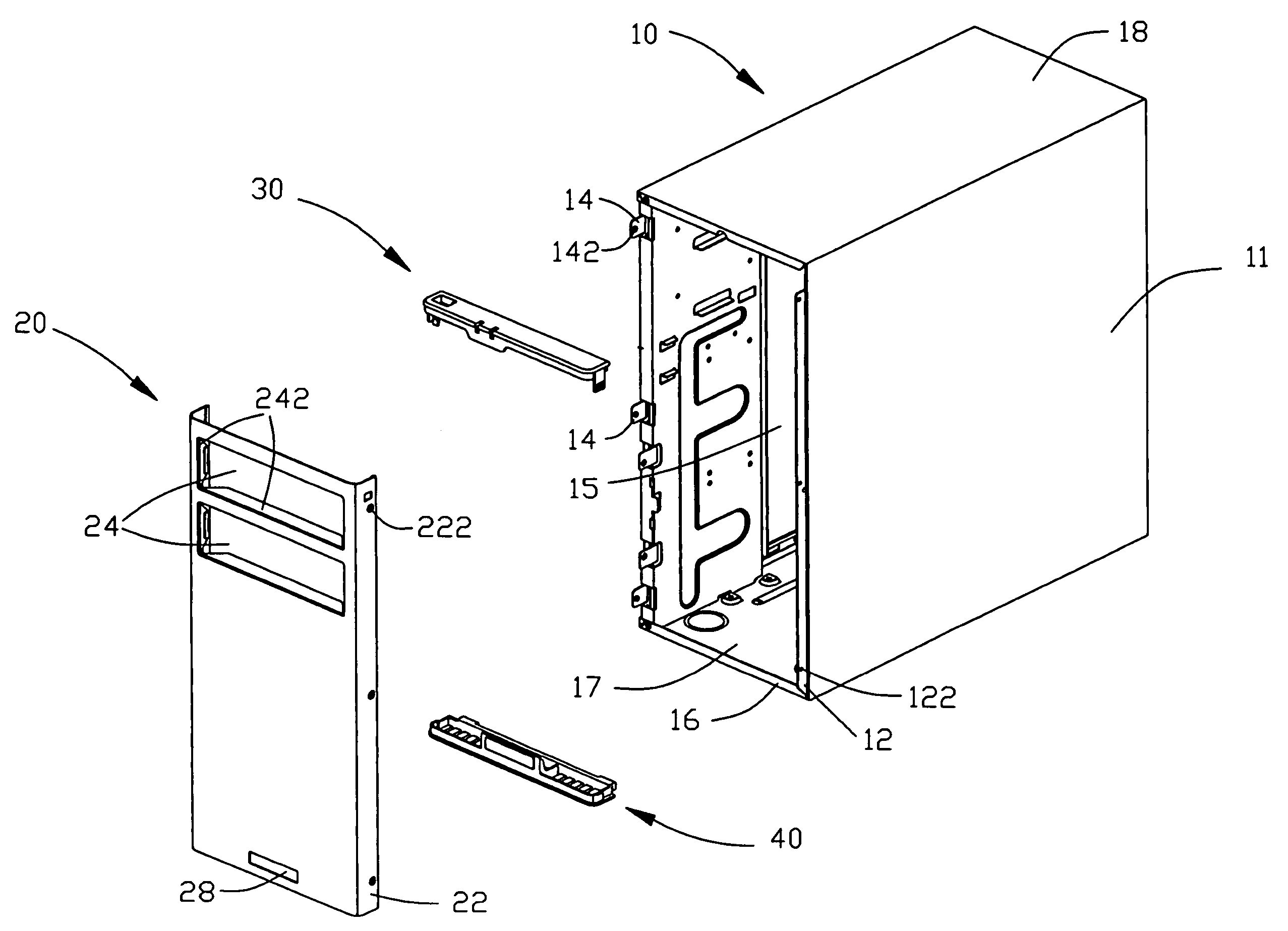
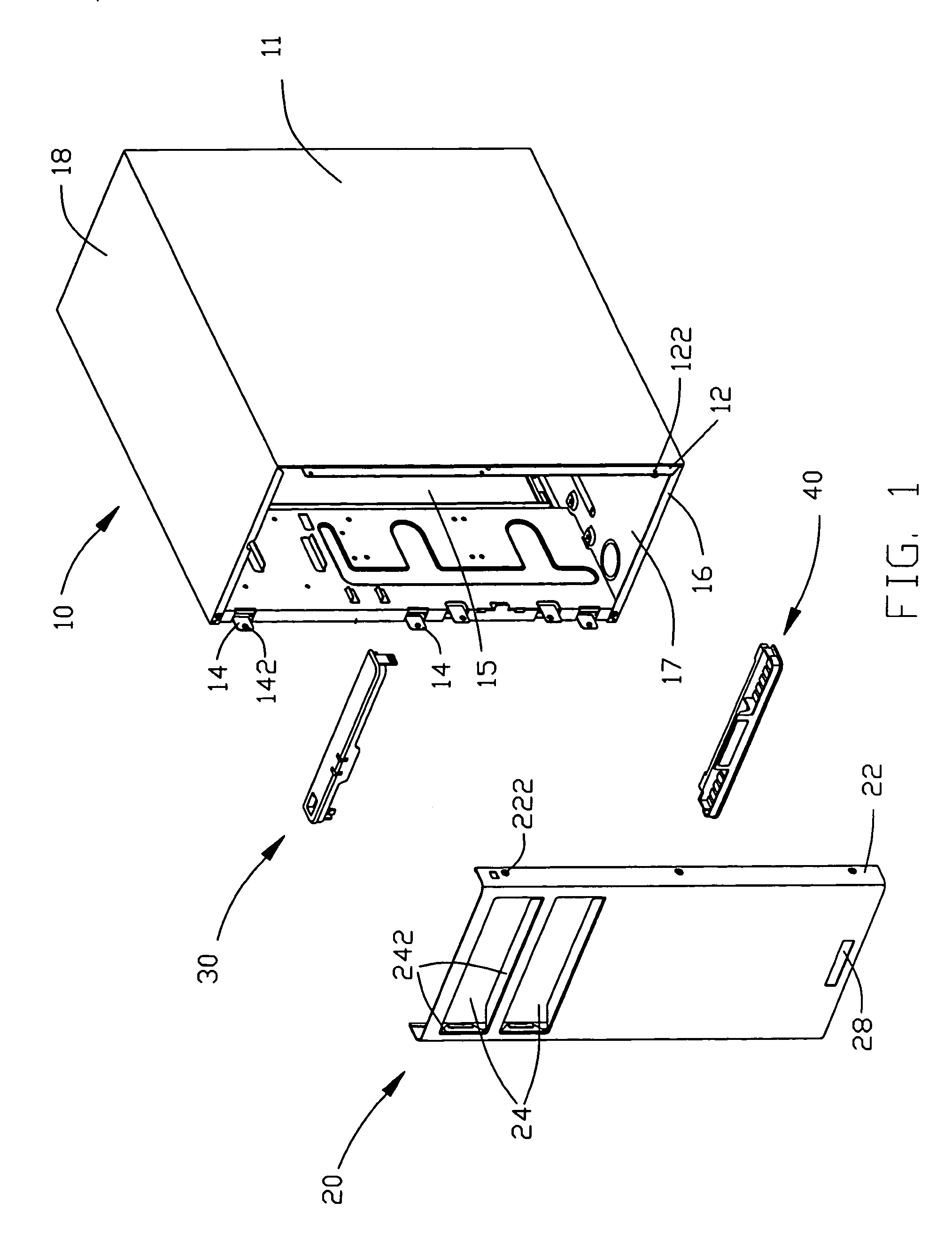
[0014]Referring to FIG. 1, an enclosure of an electronic device like a computer includes a cage 10, a front bezel 20 attached to the cage 10, a top connecting member 30, and a bottom connecting member 40.

[0015]The cage 10 made of material for providing Electromagnetic Interference (EMI) protection includes a bottom panel 17, a top panel 18, and two side panels 11 perpendicular to the top panel 18 and the bottom panel 17. The bottom panel 17, the top panel 18, and the side panels 11 are connected with each other to form an opening 15 at the front end of the cage 10. A side flange 12 is formed at an edge of one side panel 11. A plurality of mounting holes 122 is defined in the side flange 12. A plurality of connecting clips 14 is formed on the other side panel 11. A mounting hole 142 is defined in each connecting clip 14. A bottom flange 16 is upwardly formed at a front end of the bottom panel 17.

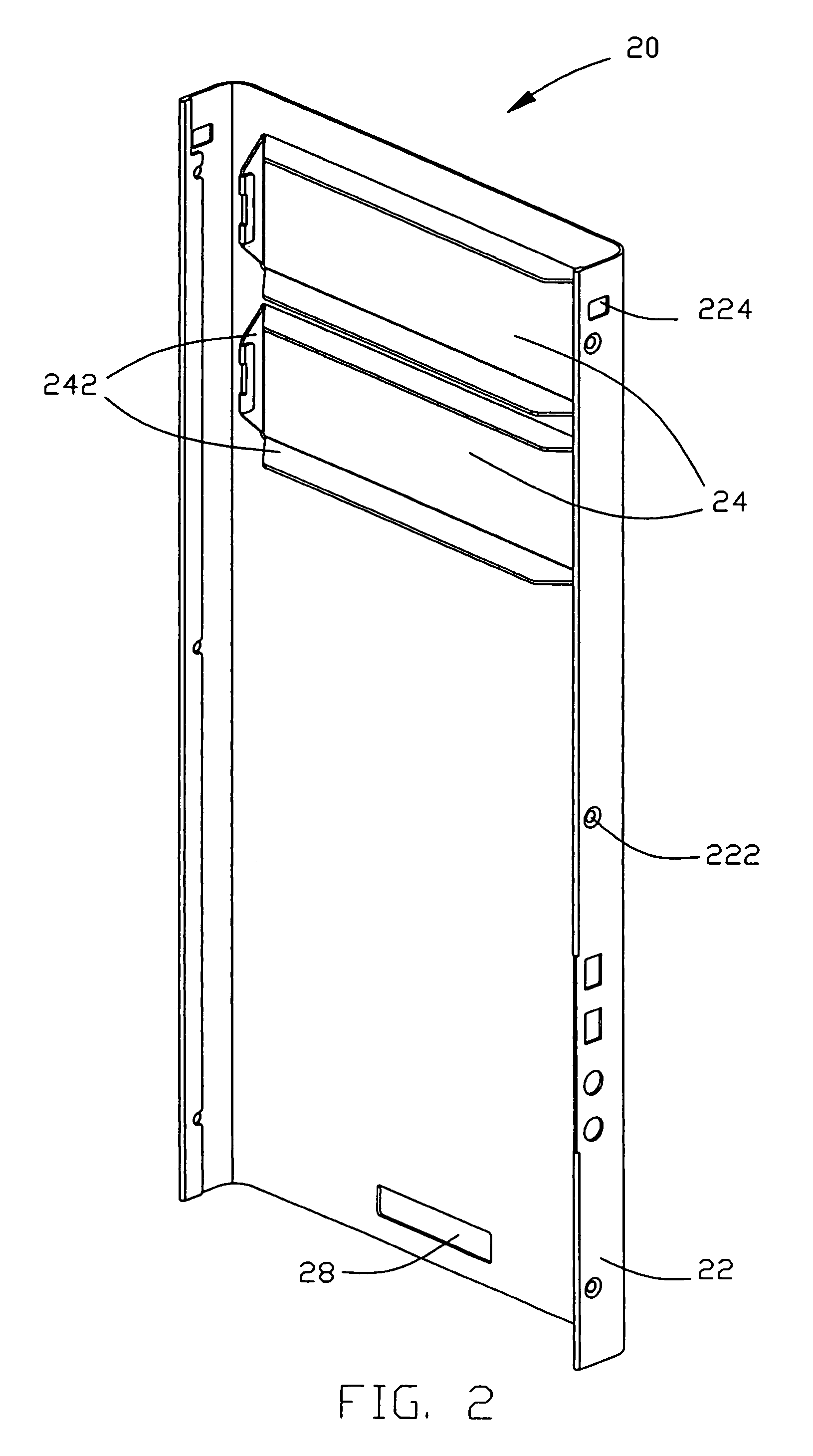
[0016]Referring also to FIG. 2, the front bezel 20 is made of the same material as the ca...


PUM


Abstract

A computer enclosure includes a cage (10) and a front bezel (20). The cage includes a top panel (18), a bottom panel (17), and a pair of side panels (11). The top panel, the bottom panel, and the side panels are connected with each other to define an opening (15). The front bezel has securing structures (222) at opposite sides thereof for securing the front bezel to the cage. The front bezel is secured to the cage for covering the opening. The computer enclosure with direct-mounting front bezel has simple structures and is inexpensive.

Description

BACKGROUND OF THE INVENTION[0001]1. Field of the Invention[0002]The present invention relates to computer enclosures, more particularly to a computer enclosure with a removable front bezel.[0003]2. General Background[0004]A conventional computer enclosure includes a cage and a bezel. The cage includes a front plate defining a plurality of locking openings and locating holes, and a bottom plate defining a pair of locking apertures. The bezel has a plurality of engaging hooks engaging with the front plate in the corresponding locking openings, and locating posts received in the corresponding locating holes. The bezel also has a pair of arcuate supporting feet. Each supporting foot includes a horizontal surface abutting against a bottom surface of the bottom plate, and a catch abutting against a top surface of the bottom plate near the corresponding locking aperture. When the bezel is attached to the cage, the supporting feet are elastically deformed to cause the bezel to be firmly att...

Claims


Application Information

Patent Timeline
Patent Type & Authority Patents(United States)
IPC IPC(8): H02G3/08
CPCG06F1/181
Inventor CHEN, YUN-LUNGSUN, DA-LONG
Owner HONG FU JIN PRECISION IND (SHENZHEN) CO LTD
Why Eureka
Try Eureka