High field head coil for dual-mode operation in magnetic resonance imaging

a magnetic resonance imaging and high field head coil technology, applied in the direction of diagnostic recording/measuring, using reradiation, instruments, etc., can solve the problem that the placement of a shield on the side of the surface coil does not allow good control of the coil decoupling

Inactive Publication Date: 2007-08-07
INVIVO CORP
View PDF14 Cites 23 Cited by
  • Summary
  • Abstract
  • Description
  • Claims
  • Application Information

AI Technical Summary

Problems solved by technology

However, placing a shield on the side of a surface coil does not allow good control in the coil decoupling.

Method used


Image

  • High field head coil for dual-mode operation in magnetic resonance imaging
  • High field head coil for dual-mode operation in magnetic resonance imaging
  • High field head coil for dual-mode operation in magnetic resonance imaging

Examples


Embodiment Construction

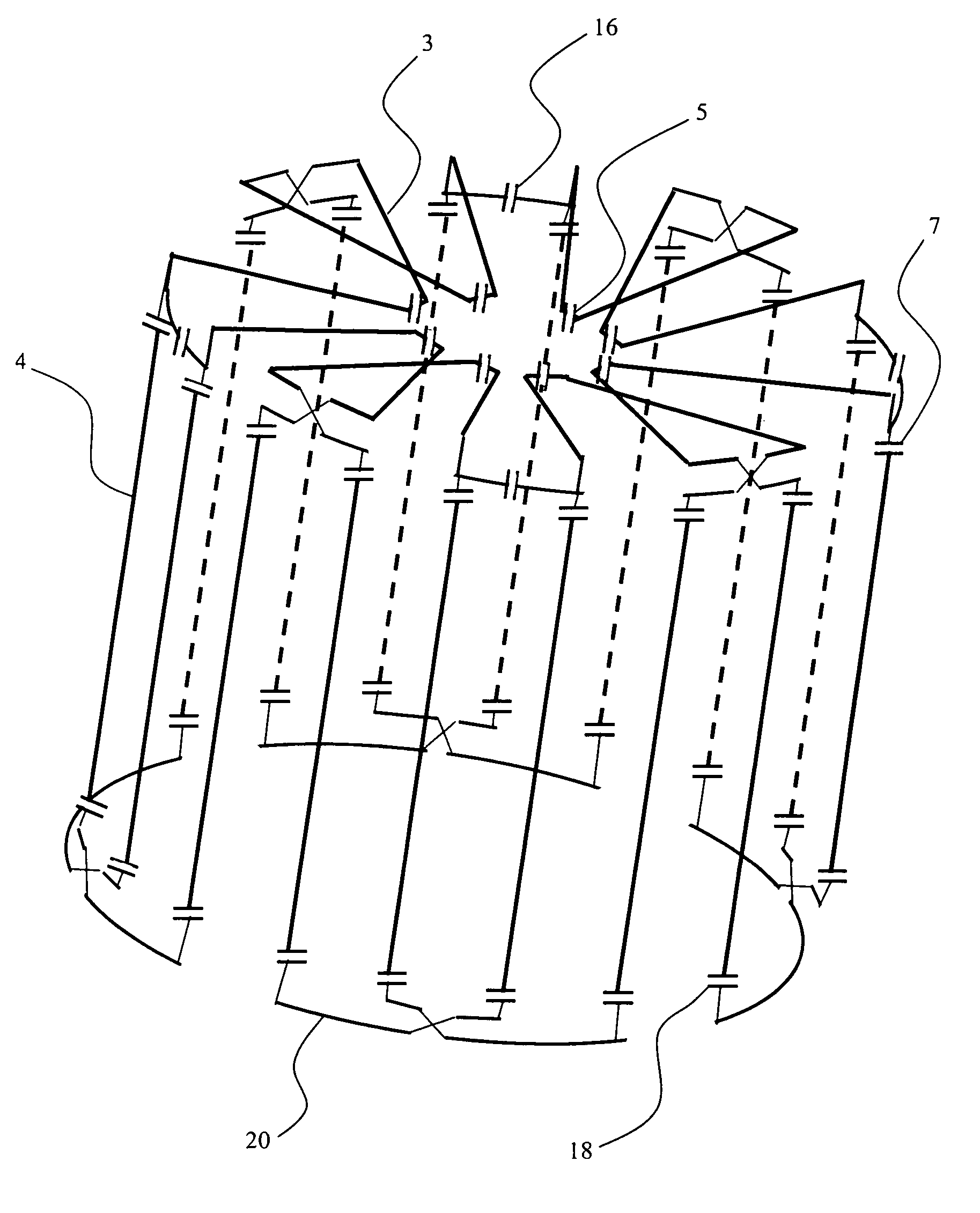
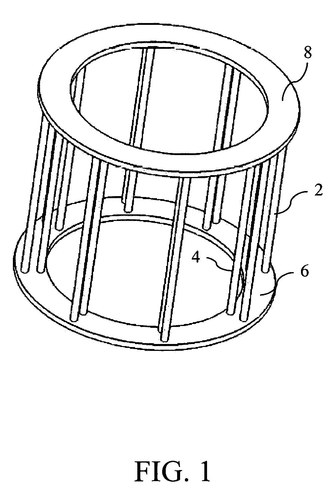
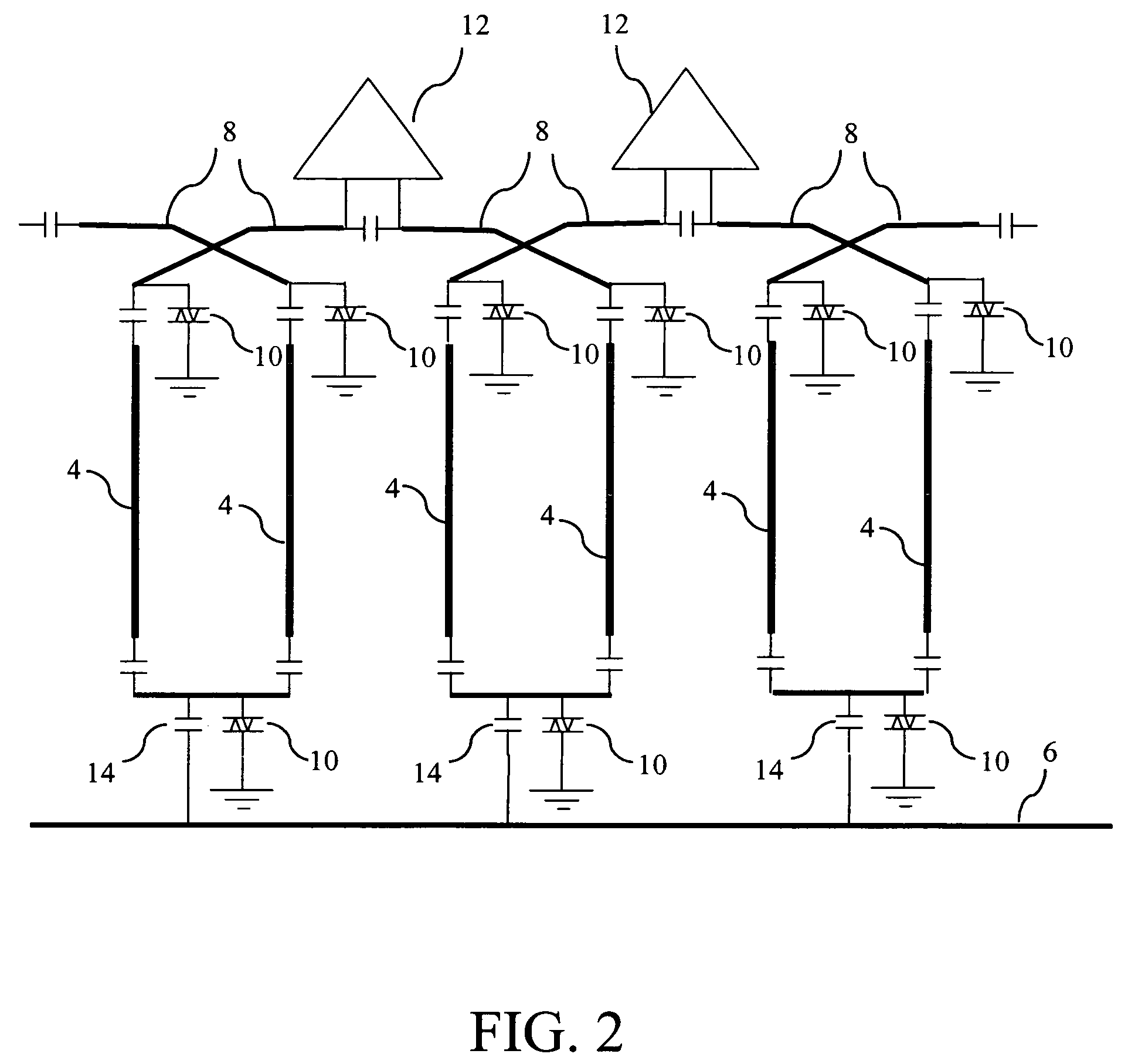
[0015]Embodiments of the subject invention can utilize a single coil structure for dual-mode operation. Embodiments of the invention pertain to a method for utilizing a single coil structure for dual mode operation. In a specific embodiment, a single coil structure can be used as a volume coil in the transmitting phase and as a phase array in the receiving phase. In an embodiment, a transmit coil array in accordance with the subject invention can be utilized for one or more of the following: 1) parallel RF excitation on an MRI scanner equipped with a multiple-channel transmitter; 2) serial RF excitation with the use of a switch system with a single channel transmitter; and 3) generation of a homogeneous B1 field for regular MRI with the use of a power splitter on a standard scanner. In a specific embodiment, the use of a concentric double loop coil with different tunings of inner and outer loops can be implemented. In an embodiment, the coil elements can be decoupled using the CRC m...


PUM


Abstract

Embodiments of the subject invention can utilize a single coil structure for dual-mode operation. In a specific embodiment, a single coil structure can be used as a volume coil in the transmitting phase and as a phase array in the receiving phase. In an embodiment, a transmit coil array in accordance with the subject invention can be utilized for one or more of the following: 1) parallel RF excitation on an MRI scanner equipped with a multiple-channel transmitter; 2) serial RF excitation with the use of a switch system with a single channel transmitter; and 3) generation of a homogeneous B1 field for regular MRI with the use of a power splitter on a standard scanner. In a specific embodiment, the use of a concentric double loop coil with different tunings of inner and outer loops can be implemented. In an embodiment, the coil elements can be decoupled using the CRC mode of a concentric double loop coil. In an embodiment, a surface coil transmit array can provide better compatibility with a receive array. In a specific embodiment, an over-coupled technique can be used to improve the phase control of the transmitting pulse.

Description

CROSS-REFERENCE TO RELATED APPLICATION[0001]The present application claims the benefit of U.S. provisional patent application Ser. No. 60 / 644,439, filed Jan. 14, 2005, which is hereby incorporated by reference herein in its entirety, including any figures, tables, or drawings.BACKGROUND OF THE INVENTION[0002]In most head coil designs, a double coil structure is used. Typically, the outside coil is a volume coil for RF excitation and the inner coil is a surface coil array for signal reception.[0003]In head imaging, two important design criteria for the coil design are homogeneity in RF excitation and sufficient sensitivity in signal reception. These requirements are usually achieved using the combination of a volume coil, such as a TEM or Birdcage coil, and a surface coil array with active decoupling circuits.[0004]It has been shown that placing a shield on the side of a surface coil can offer good decoupling. This is equivalent to the use of a counter rotating current (CRC) coil, wh...

Claims


Application Information

Patent Timeline
Patent Type & Authority Patents(United States)
IPC IPC(8): G01V3/00
CPCG01R33/34046G01R33/3415G01R33/3642G01R33/365
Inventor SAYLOR, CHARLES A.LI, YU
Owner INVIVO CORP
Why Eureka
Try Eureka