Electrical fuse circuit

a fuse circuit and circuit technology, applied in the field of electric fuse circuits, can solve the problems of increasing the number of defective memory cells, the inability of electrical fuse devices to mount for ram redundancy repair the inability of electrical fuse devices to be mounted in the system lsi, so as to reduce the number of circuits, reduce the number of shift register stages, and shorten the time for programming the fuse elements

Active Publication Date: 2007-08-07
PANASONIC SEMICON SOLUTIONS CO LTD
View PDF4 Cites 17 Cited by
  • Summary
  • Abstract
  • Description
  • Claims
  • Application Information

AI Technical Summary

Benefits of technology

[0014]The present invention is devised to solve the conventional problems. An object of the present invention is to provide an electrical fuse circuit whereby, for example, even when a number of electrical fuse elements are necessary for RAM redundancy repair, the electrical fuse elements can be easily mounted in an LSI and programming can be easily performed by blowing the electrical fuse elements with an existing general-purpose tester.

Problems solved by technology

The more memories are installed, the number of defective memory cells increases.
However, it is difficult for an existing general-purpose tester to supply a current of 10 A according to the program and supply a current of 10 A concentratedly to an electrical fuse device in an LSI chip, so that a special tester is necessary.
Thus, such an electrical fuse device cannot be mounted in a system LSI.
For this reason, such an electrical fuse device cannot be mounted for RAM redundancy repair in a system LSI.

Method used


Image

  • Electrical fuse circuit
  • Electrical fuse circuit
  • Electrical fuse circuit

Examples


embodiment 1

[0038]The following will discuss an electrical fuse circuit according to Embodiment 1 of the present invention.

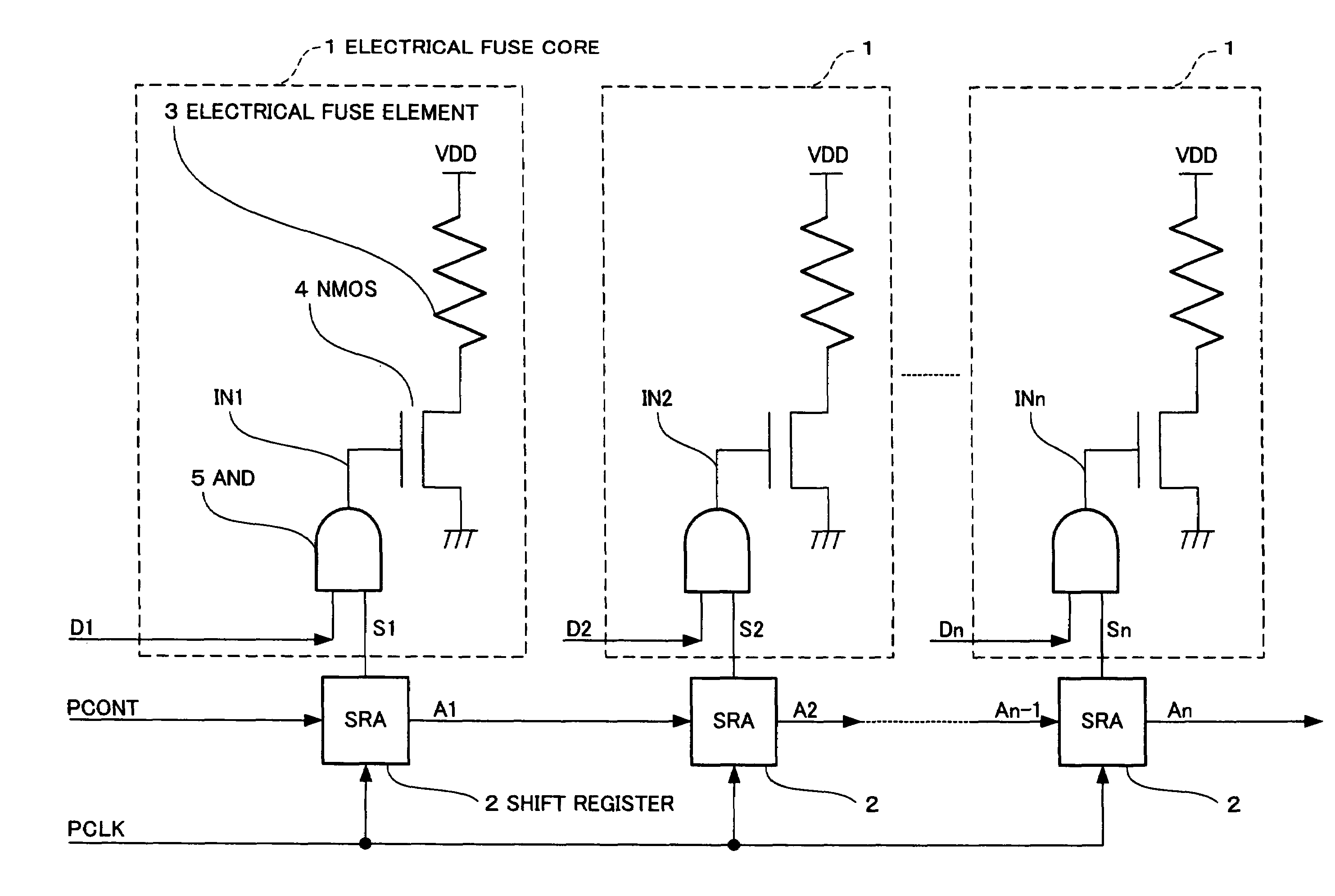
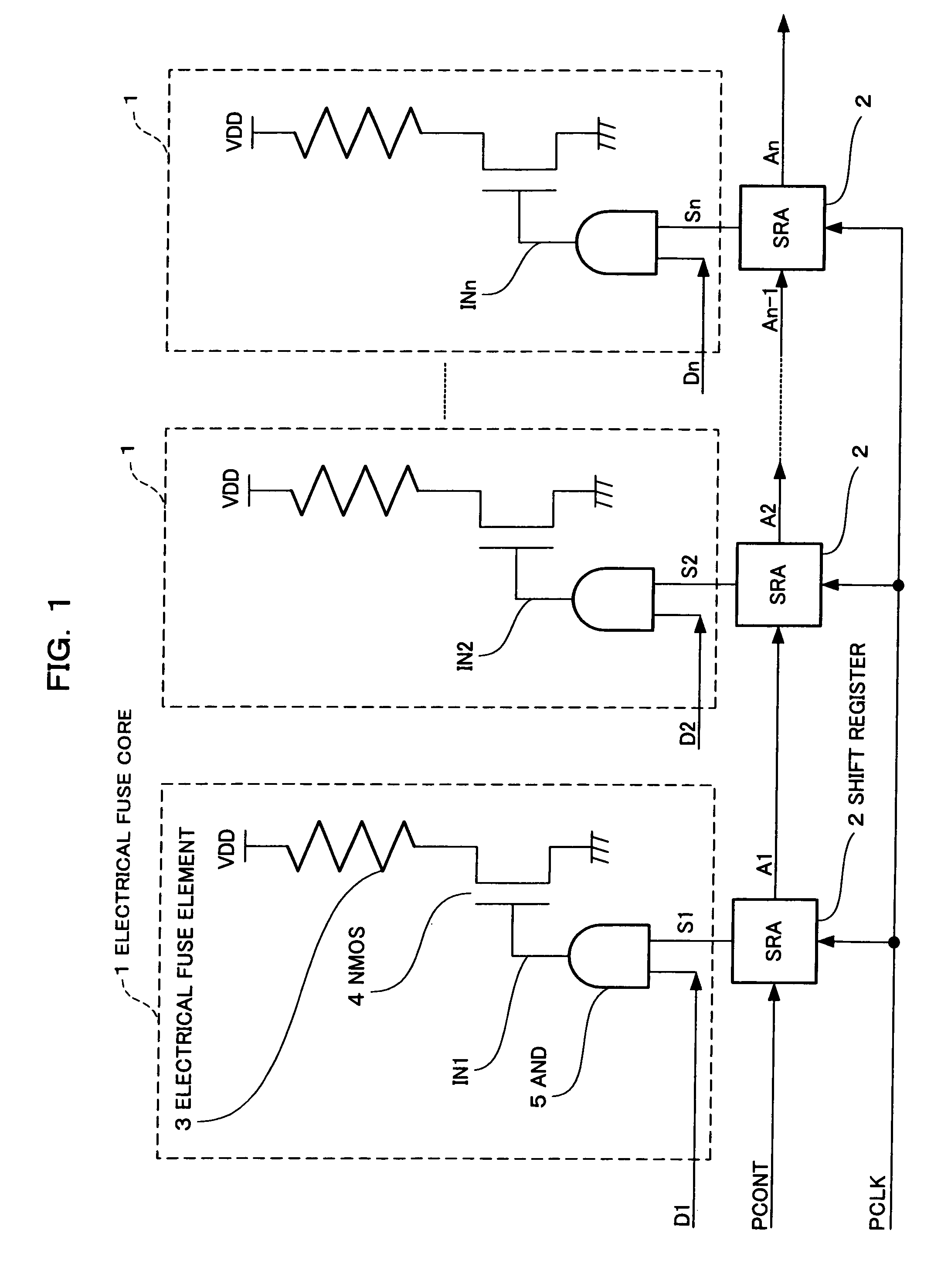
[0039]FIG. 1 is a circuit diagram showing the configuration of the electrical fuse circuit of Embodiment 1, in which two or more (n) fuse elements are configured as one module. In the electrical fuse circuit of FIG. 1, reference numeral 1 denotes n electrical fuse cores and reference numeral 2 denotes shift registers of n stages.

[0040]In the electrical fuse core 1, reference numeral 3 denotes an electrical fuse element having one end connected to a power supply (VDD), reference numeral 4 denotes an NMOS transistor which is connected in series with the electrical fuse element 3 and has its source connected to a ground terminal, and reference numeral 5 denotes a two-input AND circuit which has as its input a program data signal Di (i=1 to n) and a program enable signal Si (i=1 to n) from the shift register 2 and outputs a program signal INi (i=1 ton) to the gate of the NMOS t...

embodiment 2

[0056]The following will discuss an electrical fuse circuit according to Embodiment 2 of the present invention.

[0057]FIG. 4 is a circuit diagram showing the configuration of the electrical fuse circuit of Embodiment 2, in which two or more (n) electrical fuse elements are configured as one module. The same constituent elements as FIG. 1 are indicated by the same reference numerals.

[0058]In FIG. 4, reference numeral 20 denotes shift registers of n stages. Unlike FIG. 1, the input of the shift register 20 of the first stage is fixed at a power supply (H level). The shift registers 20 are serially connected from the first stage to the n-th stage in such a way that the output of the previous stage is connected to the input of the subsequent stage. Program enable transmission signals B1 to Bn are outputted from the respective stages. A program clock signal PCLK is connected in common from the first stage to the n-th stage of the shift registers 20. Further, program enable signals F1 to F...

embodiment 3

[0073]The following will discuss an electrical fuse circuit according to Embodiment 3 of the present invention.

[0074]FIG. 7 is a circuit diagram showing the configuration of the electrical fuse circuit of Embodiment 3, in which two or more (n) electrical fuse elements are configured as one module. The same constituent elements as FIG. 4 are indicated by the same reference numerals.

[0075]In FIG. 7, reference numeral 20 denotes shift registers of n / 4 stages. As in FIG. 4, the input of the shift register 20 of the first stage is fixed at a power supply (H level). The shift registers 20 are serially connected from the first stage to the n / fourth stage in such a way that the output of the previous stage is connected to the input of the subsequent stage. Program enable transmission signals are represented as B1 to Bn / 4. Program enable signals F1 to Fn / 4 outputted from the shift register 20 are each connected to a program enable signal shared by four of n electrical fuse cores 1. Four elec...


PUM


Abstract

An electrical fuse circuit of the present invention includes a plurality of electrical fuse cores (1) each of which has an electrical fuse element (3) and a switch transistor (4) connected in series with each other, and shift registers (2) connected to the plurality of electrical fuse cores (1) to program the electrical fuse elements (3). Program enable signals (Si) are sequentially generated and transferred by the shift registers (2), the switch transistors (4) are sequentially brought into conduct according to the program enable signals (Si) and the information of program data (Di), and the electrical fuse elements (3) are blown one by one.

Description

FIELD OF THE INVENTION[0001]The present invention relates to an electrical fuse circuit in which programming is performed by passing current through an electrical fuse element and blowing the electrical fuse element.BACKGROUND OF THE INVENTION[0002]Conventionally, electrical fuse devices (electrical fuse circuits) are configured using electrical fuse elements made of polysilicon or the like and are widely used for semiconductor integrated circuits (LSI) of trimming program devices of high-frequency semiconductor devices. In semiconductor integrated circuits including such electrical fuse devices, electrical fuse elements are blown by applying a large current of about 1 A with bipolar transistors, so that programming is performed.[0003]In recent years, for semiconductor integrated circuits, a process has been developed in which a metallic material is formed as a gate material on polysilicon by silicification and the resistance of the gate material is reduced. Accordingly, a technique...

Claims


Application Information

Patent Timeline
Patent Type & Authority Patents(United States)
IPC IPC(8): G11C17/18G11C7/00
CPCG11C17/18
Inventor SUMI, SHINICHIAGATA, YASUHIROSHIRAHAMA, MASANORIKAWASAKI, TOSHIAKINISHIHARA, RYUJI
Owner PANASONIC SEMICON SOLUTIONS CO LTD
Why Eureka
Try Eureka