Methods and systems for 2D/3D image conversion and optimization

a technology of applied in the field of methods and systems for 2d/3d image conversion and optimization, can solve the problems of reducing the refresh rate to twenty-five images per second, affecting the synchronization of both channels, and affecting the synchronization of the two channels, so as to reduce the value of the approximation variable.

Inactive Publication Date: 2007-08-07
PHOENIX 3D
View PDF30 Cites 134 Cited by
  • Summary
  • Abstract
  • Description
  • Claims
  • Application Information

AI Technical Summary

Benefits of technology

[0050]Another aspect relates to a method for generating 3D images, comprising preparing 3D image data from a first sequence of images and a second image sequence of images computed from at least two images of the first sequence using an approximation variable that changes based on a relationship between at least two images of the first sequence, and reducing the value of the approximation variable upon the occurrence of vertical disparity between at least two images of the first sequence.
[0051]Another aspect relates to an apparatus for generating 3D images, comprising means for preparing 3D image data from a first sequence of images and a second image sequence of images computed from at least two images of the first sequence using an approximation variable that changes based on a relationship between at least two images of the first sequence, and means for reducing the value of the approximation variable upon the occurrence of vertical disparity between at least two images of the first sequence.

Problems solved by technology

One particular disadvantage of sequential image transmission in connection with conventional television systems is the fact that the refresh rate is reduced to twenty-five images per second for each eye.
This creates an unpleasant flickering for the viewer.
However, problems may still arise with synchronizing both channels, as well as with the requirements placed on the receiver, which must be able to receive and process two channels simultaneously.
This is not possible for most systems generally available on the market.
In order to reduce the bandwidth required for this process, the appropriate compression methods are used; however, these create problems for stereo transmission.
For example, using block coding methods with a reasonable rate of compression, generally it is not possible to reconstruct every individual line of an image precisely.
In addition, interframe coding techniques, such as MPEG-2, do not allow transmitting or saving stereo images in a sequential image format, because image information from one image still is contained in another image, creating the so-called “crosstalk effect”, which makes clear separation of the right image from the left image difficult or impossible.
This would be possible by switching from the 3D format stored on the DVD to the 2D format stored on the DVD, but the switching may take time because usually it is not possible to switch from one scene in 3D format to the same scene in 2D format; rather it would be necessary to restart the 2D format video and to search for the scene where the 3D format of the video was stopped.
Meanwhile, the interest, emotion, suspense or intrigue created by watching the video may be lost while taking the time to make the format switch.
If such were the case, a viewer would not be able to switch between the 3D format and a 2D format.
However, upon occurrence of a hard cut, the relationship between two sequential scenes may be almost non-existent.
Absent such relation, it may be difficult, or impossible, to obtain a conversion to 3D format or at least to a sequence of images that may be comfortably viewed by a viewer.
The occurrence of a hard cut may disrupt smooth conversion of images from 2D format to 3D format.
Such disruption may lead to a less than optimum 3D viewing experience for the viewer.
Vertical motion effect in images, e.g., movies, etc., that are converted from 2D format to 3D format can be somewhat disadvantageous.
Accordingly, viewing images with vertical motion in 3D format may present a less than optimal 3D viewing experience for the viewer and also may inaccurately represent the actual depth information.
If the same 2D to 3D conversion technique, variables, values, etc., were used to convert an action movie as would be used to convert a television talk show from 2D format to 3D format, substantial effect of the 3D images may be lost during at least part of the program.
However, if the same approached were used convert a talk show program from 2D format to 3D format, the depth or 3D effect may be much less than in the action movie or, in any event, it may take much longer for the depth or 3D effect to become evident to a viewer from the 3D format images of the talk show program.

Method used


Image

  • Methods and systems for 2D/3D image conversion and optimization
  • Methods and systems for 2D/3D image conversion and optimization
  • Methods and systems for 2D/3D image conversion and optimization

Examples


Embodiment Construction

Introduction

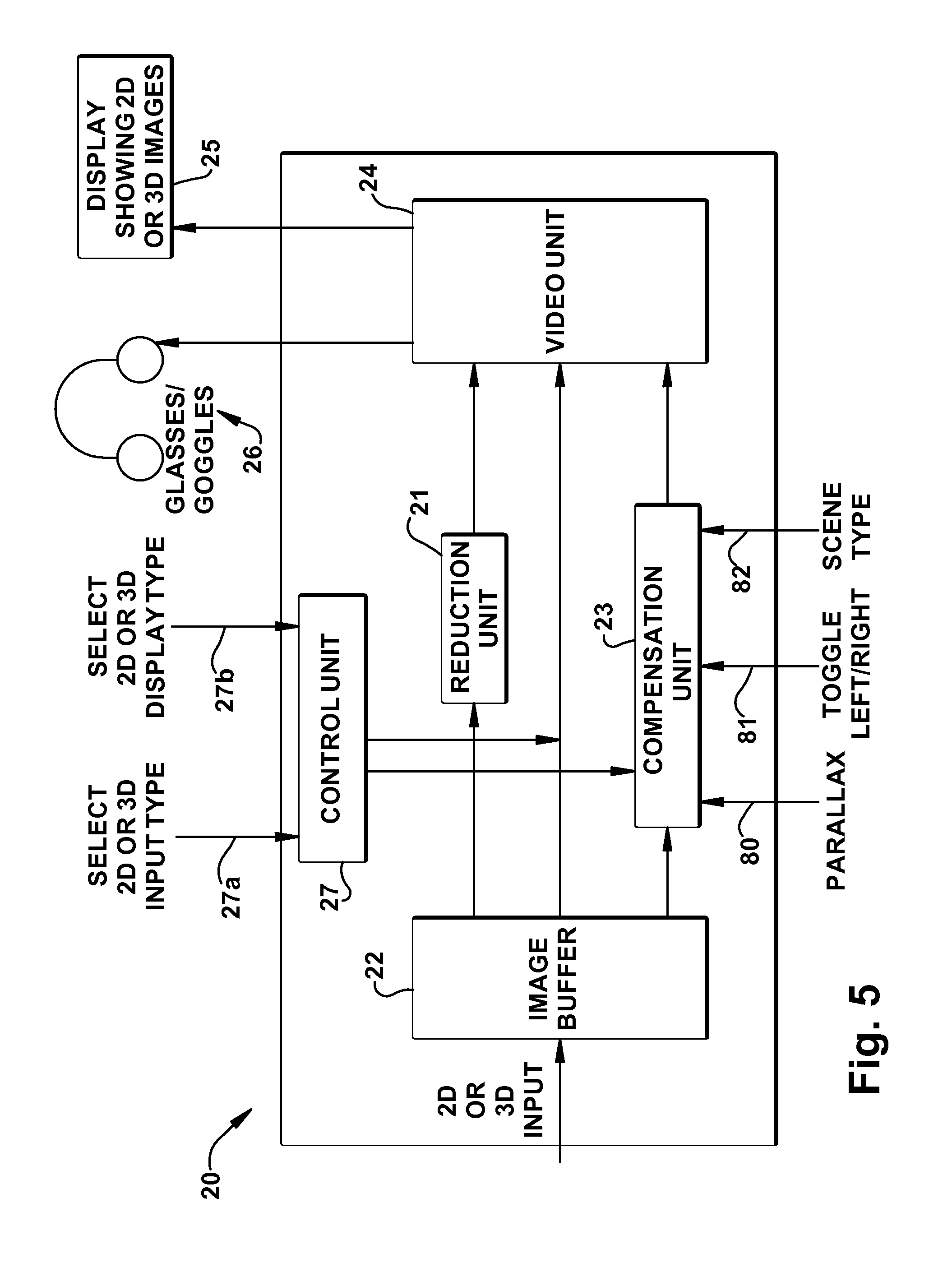
[0085]The present invention concerns improvements for converting 2D format movies, videos, televison programs, video games, etc. to 3D (three-dimensional or stereo) format to obtain a 3D effect when observed by a viewer. The invention also concerns converting 3D format movies, videos, television programs, video games, and the like to 2D format.

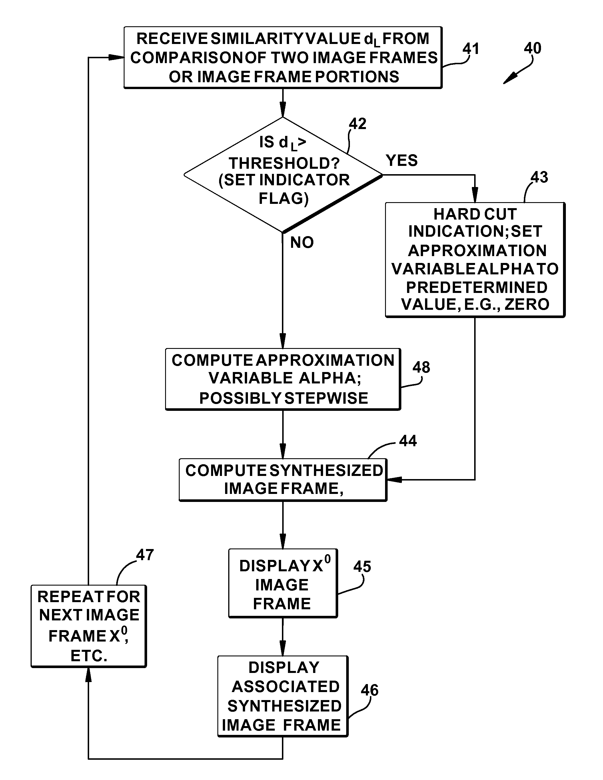
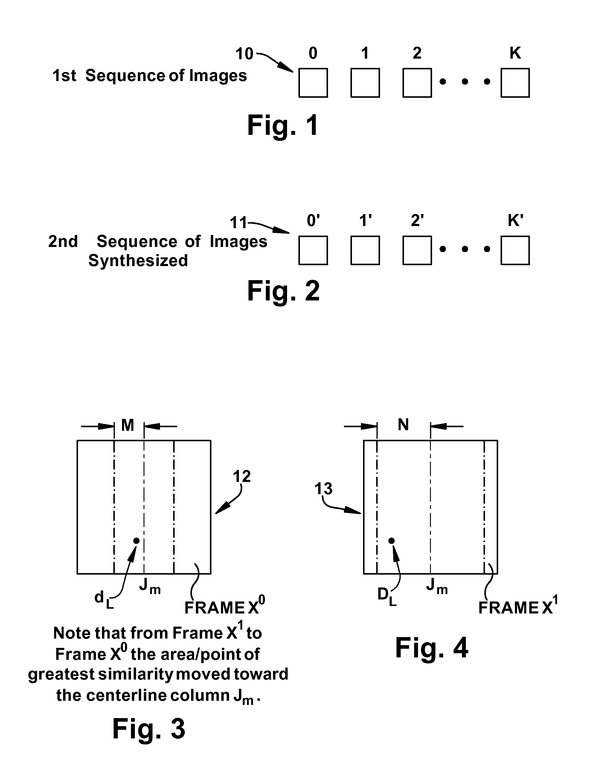
[0086]An example of an approach for converting 2D format movies to 3D format is schematically illustrated in FIGS. 1 and 2 and also is described in greater detail further below in this specification at the section entitled 2D TO 3D CONVERSION USING APPROXIMATION VARIABLE α and in the German patent application and two PCT patent applications identified at the very beginning of this patent application.

[0087]Briefly, as is illustrated in FIGS. 1 and 2, there is shown at 10 a first sequence of k images 0, 1, 2, 3 . . . K. The 0th image is the one currently being shown / displayed or is ready to be shown / displayed—sometimes referred to as...


PUM


Abstract

A method that improves compensation for hard cuts and/or vertical motion effects in the conversion of 2D images to 3D images, displays 2D images to one eye and computed images to the other eye. Generating the computed images includes using an approximation variable that represents some relationship between the 2D images, such as the speed of motion across two images. Compensating for the hard cut or vertical motion effect includes temporarily setting the approximation variable to a value that makes the left and right eye images more similar (if identical, displaying a 2D image). The approximation variable can be pre-set to a value based on the speed of motion in a scene to be displayed. A method of displaying images in either 2D or 3D may include converting 3D images to 2D images by displaying images computed from images intended for either the left eye or the right eye.

Description

[0001]This is a continuation-in-part of U.S. patent application Ser. No. 10 / 240,556, filed Oct. 1, 2002, which is a National Stage of International Application No. PCT / EP01 / 03707, filed Apr. 1, 2001. The international application was published in the German language.[0002]This application incorporates by this reference the entire disclosures of pending U.S. patent application Ser. No. 10 / 240,556, filed Oct. 1, 2002, and its predecessors, namely, PCT Patent Application No. PCT / EP01 / 03707, filed Apr. 1, 2001, and German Patent Application No. 10016074.3, filed Apr. 1, 2000.[0003]This patent application also incorporates by this reference the entire disclosure of PCT Patent Application No. PCT / EP01 / 13674, filed Nov. 24, 2001.FIELD OF THE INVENTION[0004]The invention relates to methods and devices for the generation of three-dimensional (referred to as “3D” from this point forward) images, for the generation of 3D images from two-dimensional (referred to as “2D” from this point forward)...

Claims


Application Information

Patent Timeline
Patent Type & Authority Patents(United States)
IPC IPC(8): G06K9/00H04N13/211H04N13/221
CPCH04N13/0022H04N13/0221H04N13/026H04N13/0454H04N13/221H04N13/359H04N13/128H04N13/261H04N13/211
Inventor NASKE, ROLF-DIETERSCHWARTZ, STEVEN M.HOPEWELL, WILLIAM
Owner PHOENIX 3D
Why Eureka
Try Eureka