
Optical fiber interferometer with relaxed loop tolerance and QKD system using the same

a technology of optical fiber and loop tolerance, applied in the field of optical fiber-based interferometers and quantum key distribution systems using the same, can solve problems such as undergoing a relative time delay

Active Publication Date: 2007-08-07
MAGIQ TECH INC
View PDF1 Cites 3 Cited by
  • Summary
  • Abstract
  • Description
  • Claims
  • Application Information

AI Technical Summary

Benefits of technology

"The invention is an optical fiber interferometer that uses a special section of optical fiber to compensate for differences in optical path length between two loops of optical fiber. This interferometer is useful in a quantum key distribution system, which uses single-photon detectors to detect interfered optical signals. The invention also includes a method for forming the interferometer. The technical effects of this invention include improved accuracy and stability in quantum key distribution systems, as well as improved performance and reliability of optical fiber interferometers more generally."

Problems solved by technology

The orthogonally polarized optical signals travel at different speed down the fiber due to the fast and slow optical axes and thus undergo a relative time delay.

Method used


Image

  • Optical fiber interferometer with relaxed loop tolerance and QKD system using the same
  • Optical fiber interferometer with relaxed loop tolerance and QKD system using the same
  • Optical fiber interferometer with relaxed loop tolerance and QKD system using the same

Examples


example application

[0037]The optical fiber interferometer of the present invention is useful for any application that would benefit from relaxing the tolerances on cutting the optical fiber sections that make up one or more of the interferometer loops.

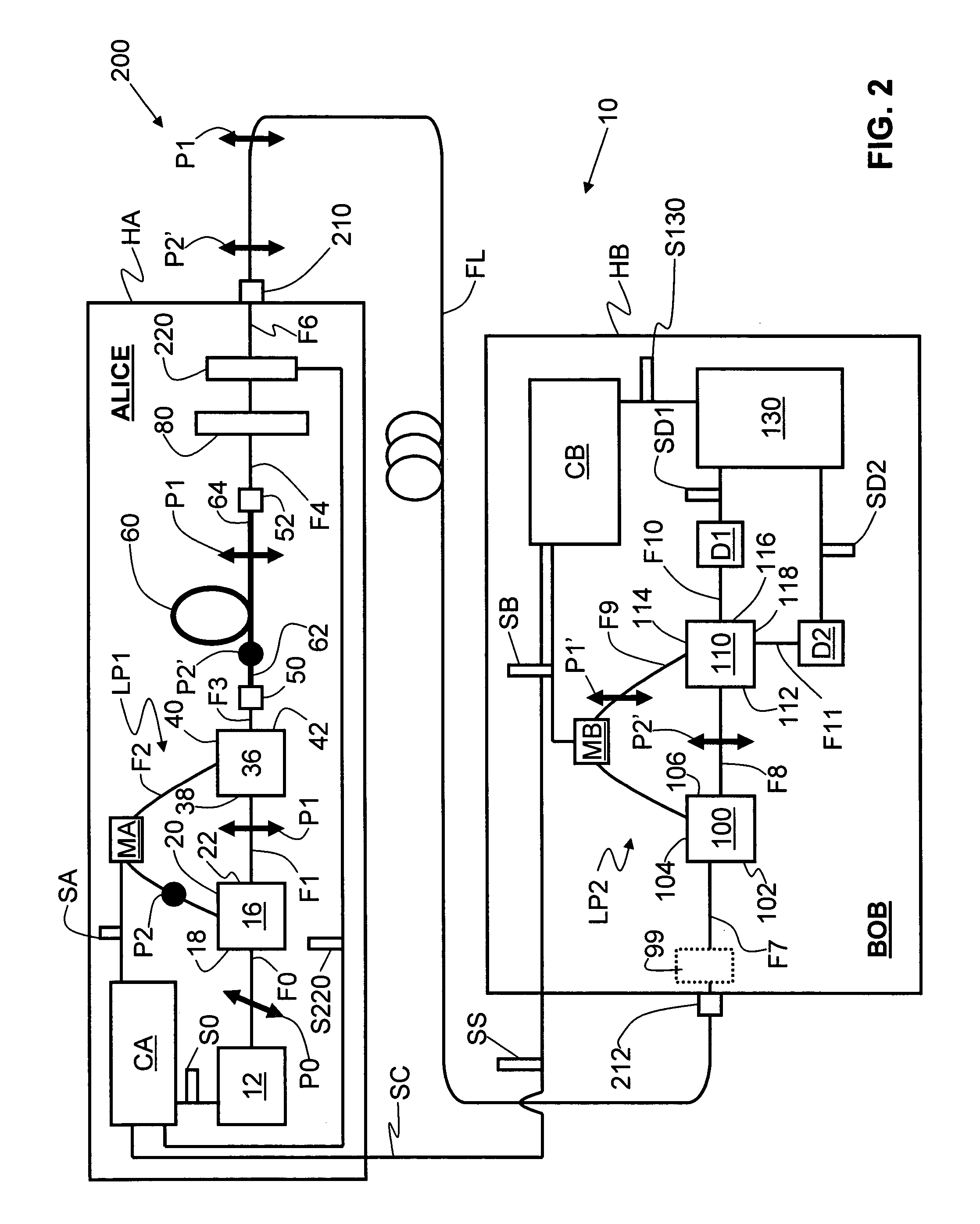
[0038]An example application for the optical fiber interferometer of the present invention is for a QKD system. FIG. 2 is a schematic diagram of a QKD system 200 based on optical fiber interferometer 10 discussed above in connection with FIG. 1. QKD system 200 includes all of the above-mentioned elements of optical fiber interferometer 10, as well as additional elements that make up the QKD system, as described below.

[0039]QKD system 200 includes two QKD stations Alice and Bob. Alice includes light source 12, first loop LP1, first optical fiber coupler 50, PM optical fiber section 60, second optical fiber coupler 52, and polarization-adjusting member 80, all enclosed in a secure housing HA. Alice further includes a phase modulator MA arranged in optical ...


PUM

PropertyMeasurementUnit
length L60aaaaaaaaaa
optical path lengthaaaaaaaaaa
lengthaaaaaaaaaa

Abstract

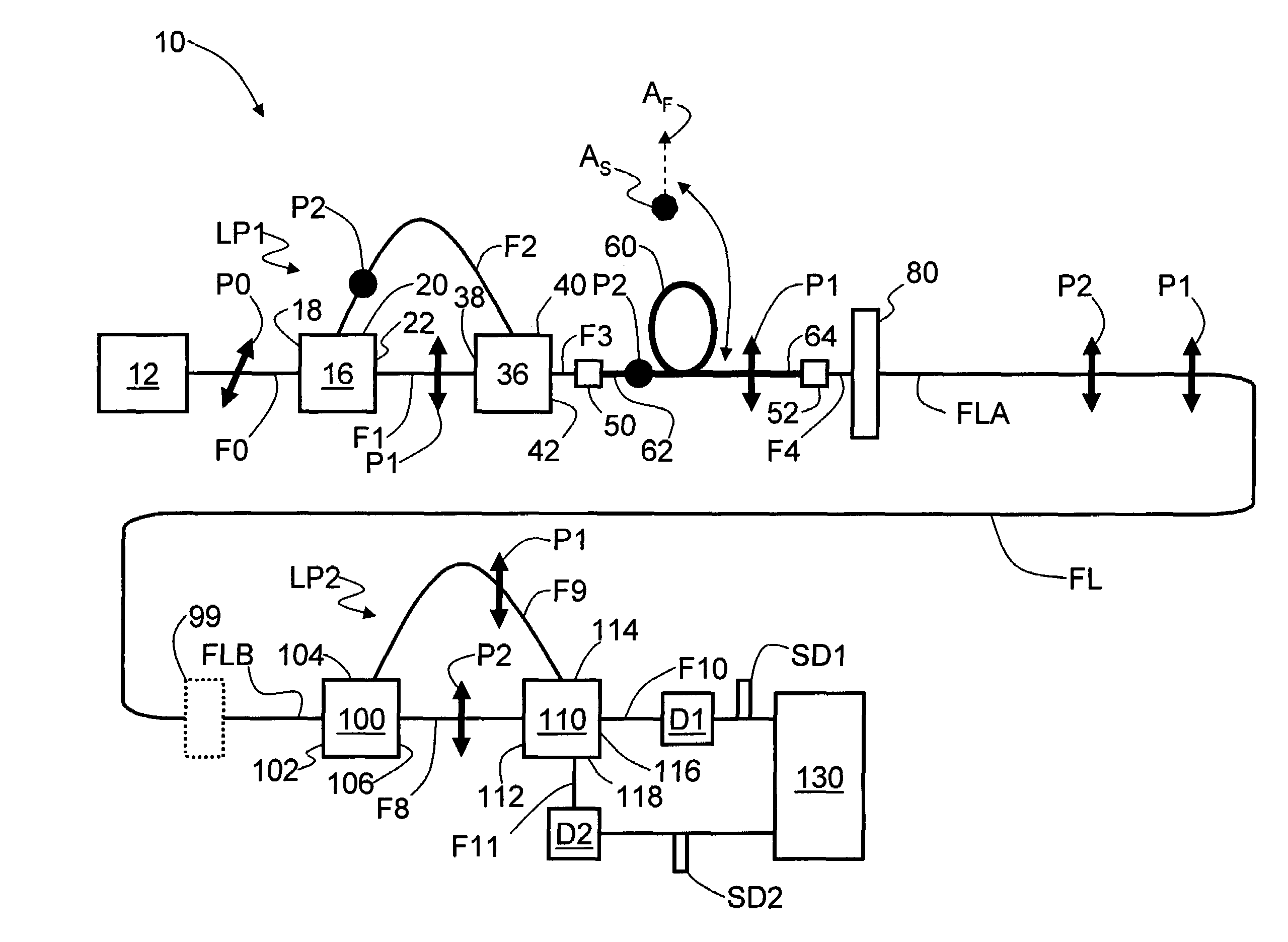
An optical fiber interferometer (10) with relaxed loop tolerance, and a quantum key distribution (QKD) system (200) using same is disclosed. The interferometer includes two optical fiber loops (LP1 and LP2). The loops have an optical path length (OPL) difference between them. A polarization-maintaining (PM) optical fiber section (60) of length (L60) and having fast and slow optical axes (AF and AS) optically couples the two loops. The length and fast-slow axis orientation is selected to introduce a time delay (ΔT1-2) between orthogonally polarized optical pulses traveling therethrough that compensates for the OPL difference. This allows for drastically relaxed tolerances when making the loops, leading to easier and more cost-effective manufacturing of the interferometer as well as related devices such as a optical-fiber-based QKD system.

Description

FIELD OF THE INVENTION[0001]The present invention relates to interferometry, and in particular to optical-fiber-based interferometers and quantum key distribution (QKD) systems using same.BACKGROUND OF THE INVENTION[0002]An optical interferometer is a device that splits and later recombines coherent optical signals to make a measurement based on information (e.g., phase information) encoded in one or both of the optical signals. Optical interferometers are employed in a number of measurement-related applications, such as making precise measurements of surface topography, measuring precise distances between two objects, or measuring small amounts of motion.[0003]There are a number of high-precision devices based on optical interferometers. One such device is the ring laser gyroscope used in navigation systems for airplanes and missiles. Another such device of is quantum key distribution (QKD) system used in quantum cryptography. This latter device is discussed in detail below and is ...

Claims


Application Information

Patent Timeline
Patent Type & Authority Patents(United States)
IPC IPC(8): G02F1/35G01B9/02G02B6/26G02B6/28H04L9/00
CPCH04L9/0858G02B6/2861
Inventor TRIFONOV, ALEXEIBEAL, A. CRAIG
Owner MAGIQ TECH INC
Learn More