Pinch valve

a technology of pinch valve and valve body, which is applied in the direction of diaphragm valve, valve details, valve arrangement, etc., can solve the problems of large operation error, difficult fine adjustment, strength and processing precision,

Inactive Publication Date: 2007-08-14
ASAHI YUKIZAI KOGYO CO LTD
View PDF11 Cites 20 Cited by
  • Summary
  • Abstract
  • Description
  • Claims
  • Application Information

AI Technical Summary

Benefits of technology

[0006]The present invention has been made in consideration with the above problems of the prior art, and an object thereof is to provide a pinch valve enabling fine adjustment of the opening degree, that is, fine adjustment of the flow rate, in a conventional pitch valve, more precisely and easily.
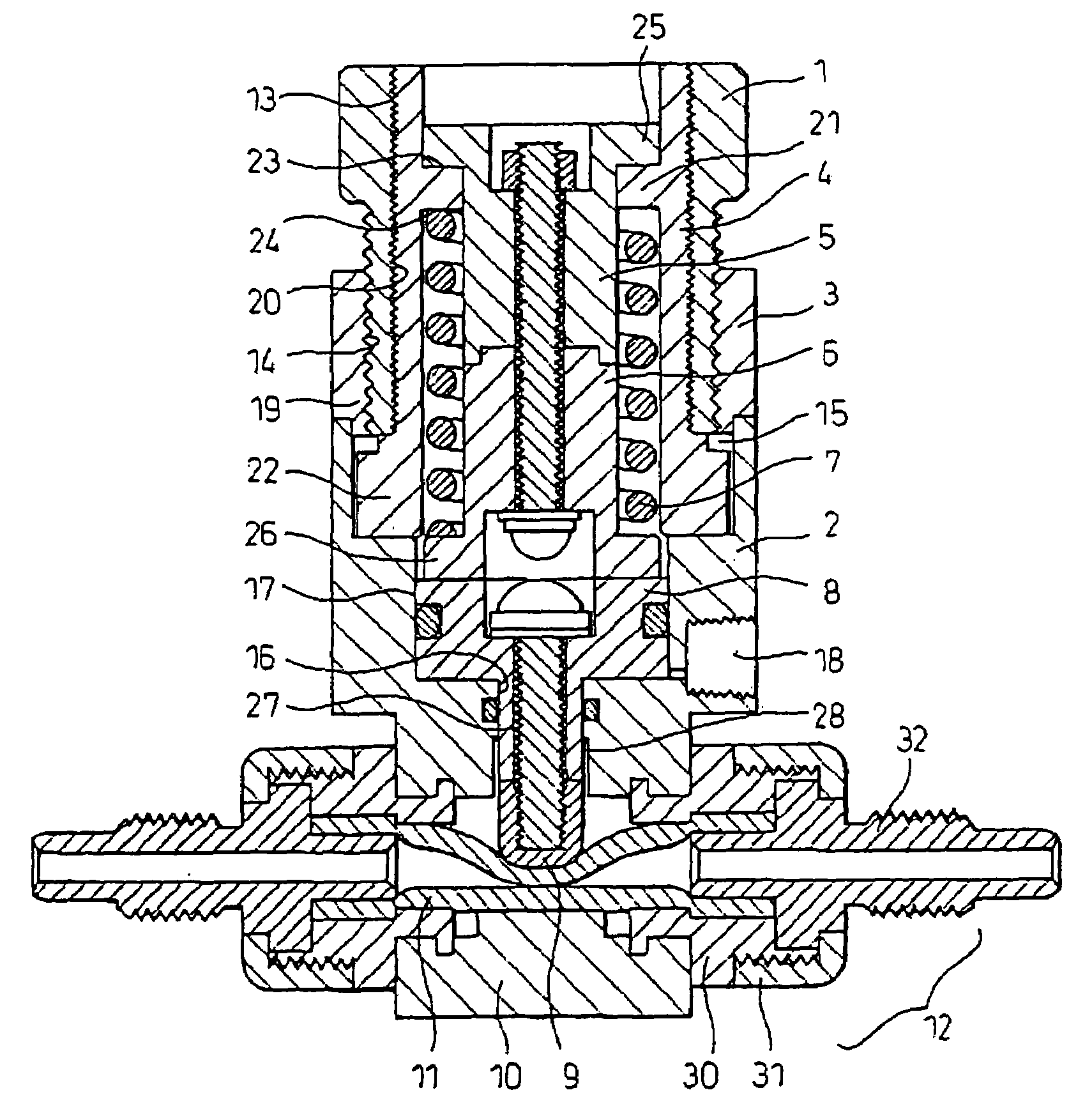
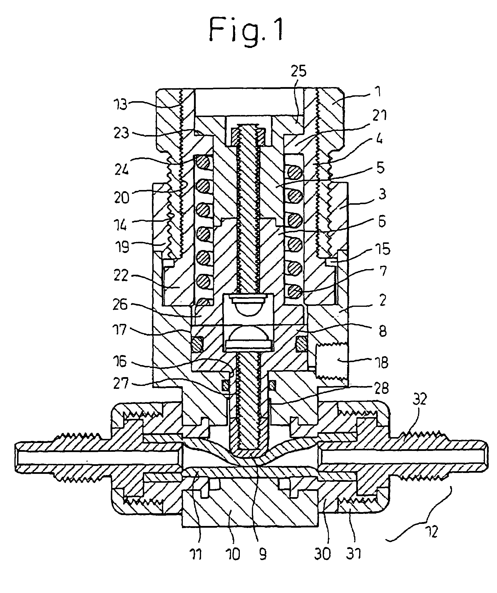
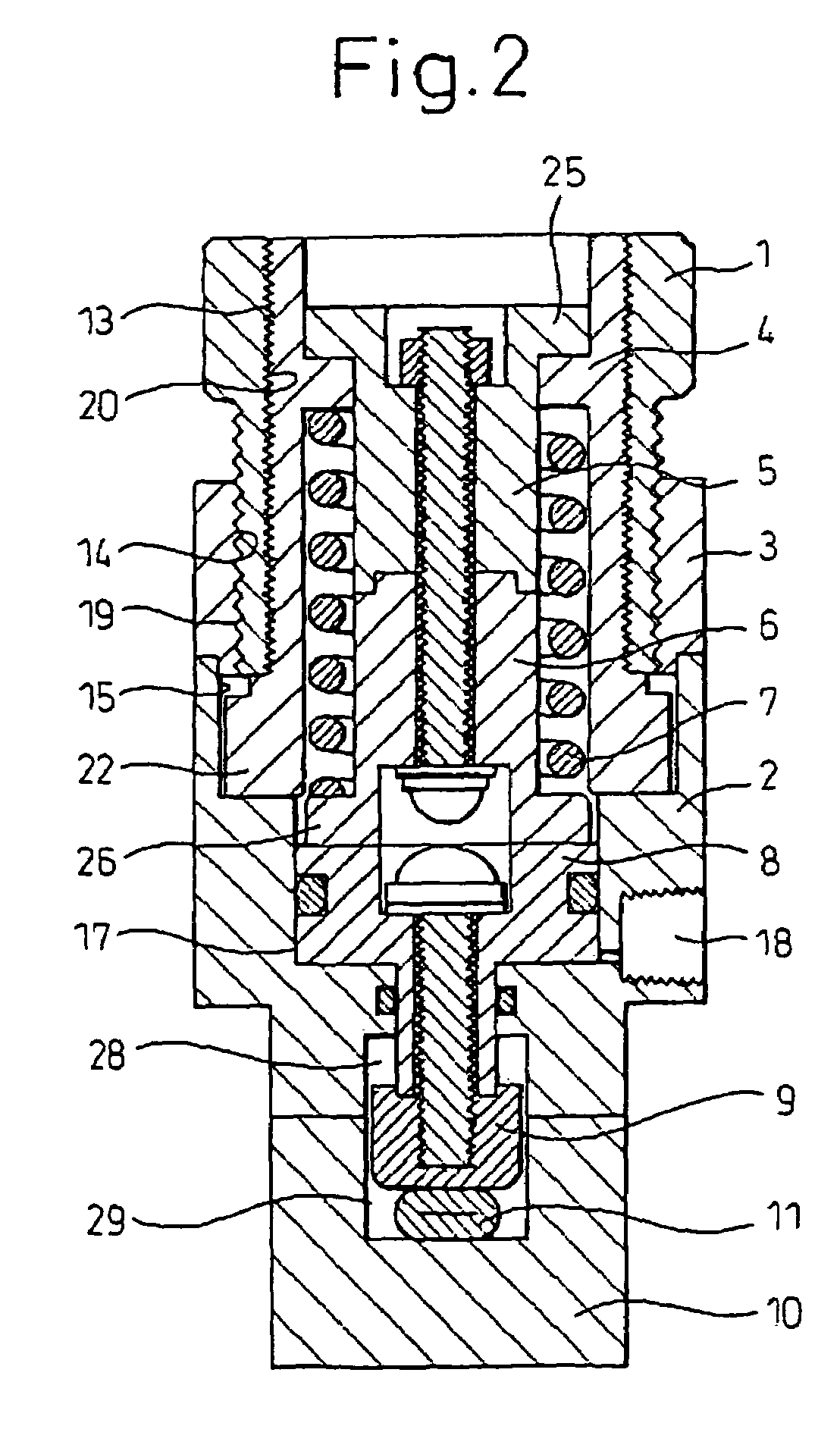
[0008]The feature of the present invention lies in the point of forming screw portions on the inner periphery and the bottom of the outer periphery of a single cylinder handle and increasing the pitch of the male screw portion formed on the bottom of the outer periphery of the handle from the pitch of the female screw portion formed on the inner periphery of the handle. Due to this, when the handle is turned by one turn, the handle rises or descends by exactly the pitch of the male screw portion with respect to the handle support portion screwed with the male screw portion formed on the outer periphery of the handle and the cylinder body connected to the same, while the hollow stem screwed with the female screw portion of the inner periphery of the handle moves in the reverse direction from the handle by exactly the pitch of the female screw portion with respect to the handle. That is, the hollow stem moves relative to the handle support portion and the cylinder body by exactly the pitch difference between the female screw portion and the male screw portion of the handle due to one turn of the handle, so that the position of the hollow stem can be changed by exactly a fine amount. On the other hand, due to the interaction between the annular projection of the hollow stem, the spring, and the two flanges of the piston pusher, the vertical position of the hollow stem defines the vertical position of the piston pusher and defines the opening degree of the tube body by the pressing piece via the piston. Therefore, according to the structure of the pinch valve of the present invention, fine adjustment of the position of the hollow stem in the vertical direction can be achieved, so that fine adjustment of the opening degree of the tube body (that is, the valve opening degree) can be achieved by the pressing piece via the piston.
[0010]Preferably, a pitch difference between the female screw portion and the male screw portion of the handle may be set in a range of from 1 / 20 to ⅕ of the pitch of the male screw portion. If the pitch difference is smaller than 1 / 20 of the pitch of the male screw portion, the stroke of the handle becomes too large and the valve height becomes larger. Further, if the pitch difference is larger than ⅕ of the pitch of the male screw portion, fine adjustment of the valve opening degree becomes no longer possible. By selecting the pitch difference between the male screw portion and the female screw portion in the above range, it is possible to adjust the stroke of the handle as desired, so fine adjustment of a broad range of opening degree becomes possible.
[0011]Alternatively, preferably, an inner periphery of a portion between the handle support portion and the cylinder portion of the cylinder body is formed with a recess, and the hollow stem has a flange accommodated in the recess of the cylinder body at a bottom end thereof. Accommodating the flange of the hollow stem in the recess of the cylinder body allows the hollow stem to be moved up and down by turning the handle, while preventing it to turn with respect to the cylinder body.
[0013]Alternatively, preferably, connecting portions for connecting the tube body to another tube are provided at the two sides of the main body. These connecting portions make it easy to connect the pinch valve to an outside flow passage.

Problems solved by technology

This results in the large operation error and therefore makes fine adjustment difficult.
To enable finer adjustment, it is sufficient to make the pitch of the male screw portion of the handle 1 smaller, but making the pitch smaller causes problems in strength and in processing precision and therefore is limited.

Method used


Image

  • Pinch valve
  • Pinch valve
  • Pinch valve

Examples


Embodiment Construction

[0026]Although several embodiments of the present invention will be described below with reference to the accompanying drawings, but the present invention is of course not limited to these embodiments.

[0027]A pinch valve made of PVDF according to the present invention will be described with reference to the accompanying drawings.

[0028]Reference numeral 1 designates a cylindrical handle, which is provided with a female screw portion 13 formed at the inner periphery thereof and provided with a male screw portion 14 formed at the bottom outer periphery thereof by a pitch larger than the pitch of the female screw portion 13 and reduced in diameter from the top end of the handle (see FIGS. 1 and 3).

[0029]Reference numeral 2 designates a closed-bottom tube shaped cylinder body, which is provided with a recess 15 formed at the top inner periphery thereof and a cylinder portion 17 formed below the recess 15. The cylinder portion 17 is reduced in diameter from the recess 15 and has a through...


PUM


Abstract

A pinch valve is provided with a main body (10) accommodating a tube body (11), a cylinder body (2) having an upper cylinder portion (17) and a lower handle support portion (3), a piston accommodated in the cylinder portion, a pressing piece (9) fixed to the piston for pressing the tube body, a cylindrical handle (1), a hollow stem (4), and a piston pusher (5, 6). The handle has a female screw portion, and a male screw portion having a pitch larger than the pitch of the female screw portion and adapted to be screwed with the female screw portion formed on the handle support portion. The stem has a male screw portion adapted to be screwed with the female screw portion of the handle on outer periphery, and is accommodated in the cylinder body. The piston pusher is inserted into the stem so that the bottom end surface thereof comes into contact with the top end of the piston and is urged toward the piston by a spring.

Description

TECHNICAL FIELD[0001]The present invention relates to a pinch valve used in a fluid transport pipeline in various industrial fields, such as chemical factories, semiconductor production, food processing, biotechnology or the like, and more particularly, to a pinch valve which has an opening degree adjustment mechanism enabling the opening degree to be adjusted more precisely and easily.BACKGROUND ART[0002]The applicant invented a pinch valve, improved over the conventional pinch valve, which is extremely compact, enhances the durability of a tube body laid inside during valve opening / closing operations, and enables fine adjustment of the flow rate and filed an application for it previously (Japanese Patent Application No. 2001-179027). Explaining this structure with reference to FIG. 8, it is provided with a cylinder body 52 having a cylinder portion 61 having a female screw portion 60 for adjustment of the opening degree at the top inner periphery thereof and an air port 62 communi...

Claims


Application Information

Patent Timeline
Patent Type & Authority Patents(United States)
IPC IPC(8): F16K7/04F16K31/00F16K7/07F16K7/06
CPCF16K7/061F16K31/363F16K31/60
Inventor TOMIOKA, MIKIHANADA, TOSHIHIRO
Owner ASAHI YUKIZAI KOGYO CO LTD
Why Eureka
Try Eureka