Pressure balanced brush seal

a brush seal and balanced technology, applied in the field of brush seals, can solve the problems of material availability problems, degrade the seal, deleterious effects on the wear life of the seal, etc., and achieve the effect of uniform pressure distribution and uniform pressure distribution

Active Publication Date: 2007-08-14
GENERAL ELECTRIC CO
View PDF18 Cites 25 Cited by
  • Summary
  • Abstract
  • Description
  • Claims
  • Application Information

AI Technical Summary

Benefits of technology

[0005]In a further preferred embodiment of the present invention there is provided a circumferentially extending brush seal segment between static and rotary components having high and low pressure regions on opposite sides of the seal comprising: a fence carried by the static component and projecting toward the rotary component; a plurality of bristles forming a bristle pack carried by the static component on a downstream side of the fence and cantilevered toward the rotary component with tips of the bristles engaging the rotary component; a pressure plate carried by the static component on a downstream side of the bristle pack; a bristle pack backing plate carried by the static component between the bristle pack and the pressure plate; and the bristle backing plate having a plurality of slots opening through an upstream face thereof and a plurality of grooves formed on a downstream face thereof, the grooves lying in communication with selected slots of the bristle backing plate to provide a substantially uniform pressure distribution along a downstream side of the bristle pack.

Problems solved by technology

This of course degrades the seal and has other deleterious effects on the wear life of the seal.
It is also noted that suppliers of brush seal backing plate material, such as 409 stainless steel, have material availability problems as well as manufacturing difficulties in the formation of the brush seals.

Method used


Image

  • Pressure balanced brush seal
  • Pressure balanced brush seal
  • Pressure balanced brush seal

Examples


Embodiment Construction

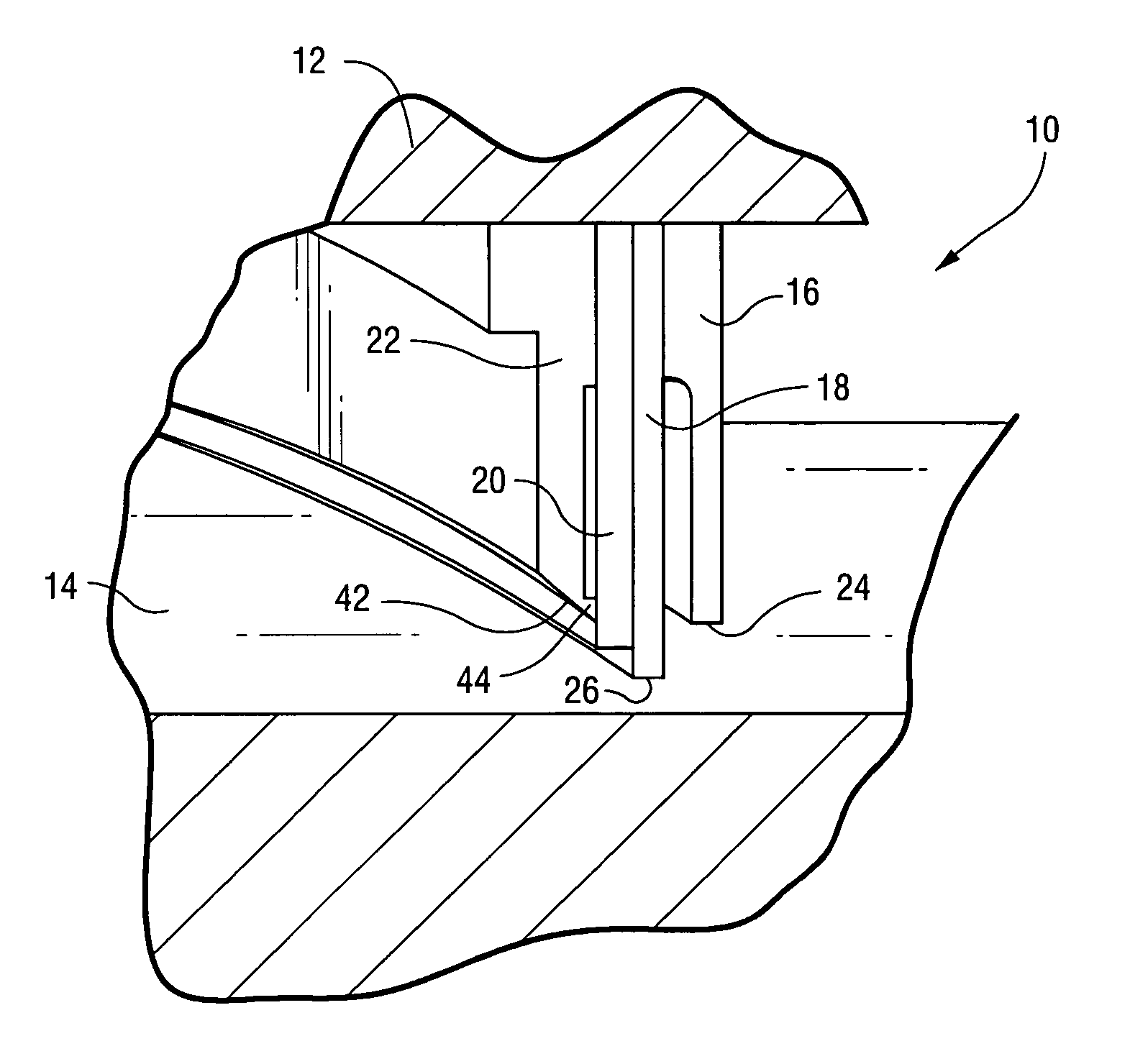
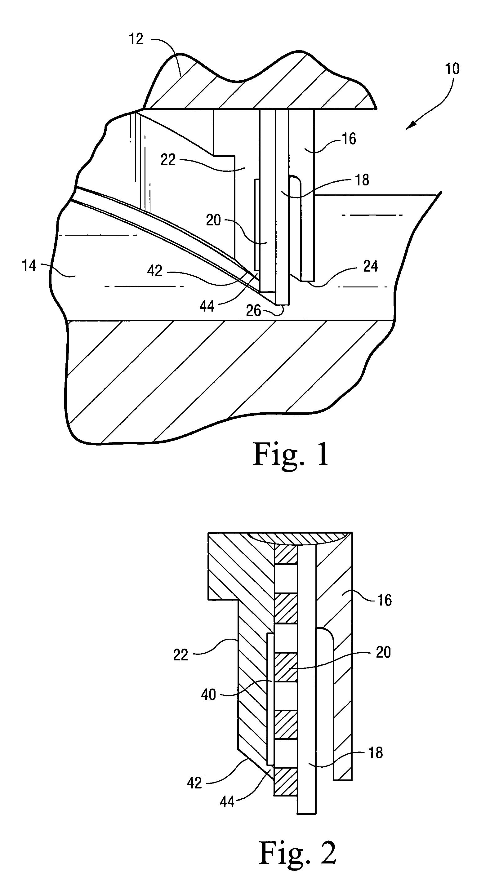
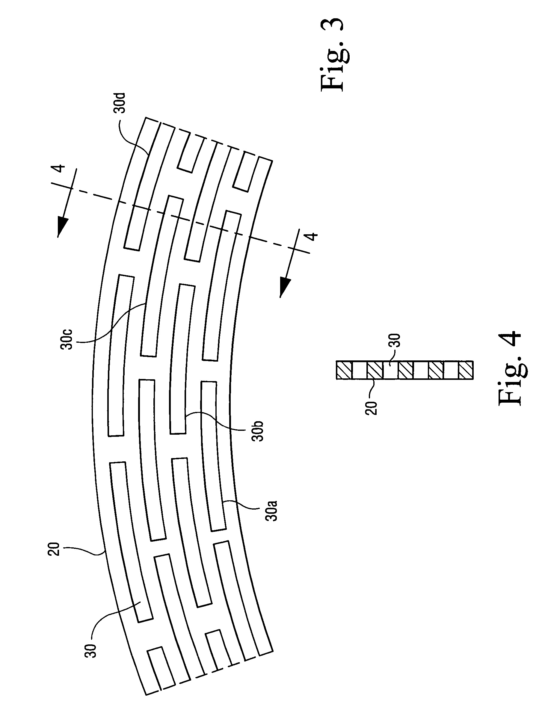
[0004]In a preferred embodiment of the present invention there is provided a circumferentially extending brush seal segment between static and rotary components having high and low pressure regions on opposite sides of the seal comprising: a fence carried by the static component and projecting toward the rotary component; a plurality of bristles forming a bristle pack carried by the static component on a downstream side of the fence and cantilevered toward the rotary component with tips of the bristles engaging the rotary component; a pressure plate carried by the static component on a downstream side of the bristle pack; a bristle pack backing plate carried by the static component between the bristle pack and the pressure plate; the bristle backing plate having a plurality of slots opening through opposite sides thereof, the pressure plate having a plurality of grooves formed on a side thereof facing the bristle backing plate, certain of said grooves lying in communication with sel...


PUM


Abstract

A brush seal extends between static and rotary components. The brush seal includes a fence on the high pressure side, a bristle pack behind the fence, a bristle pack backing plate and a pressure plate. The backing plate includes a plurality of circumferentially and radially spaced arcuate slots arrayed in staggered relation about the brush seal segment. The pressure plate includes radially extending grooves opening toward the backing plate and intersecting each of the slots along that radius to afford a substantially uniform distribution of pressure on the downstream side of the bristle backing plate. In another embodiment, the grooves extend along the downstream faces of the bristle backing plate.

Description

BACKGROUND OF THE INVENTION[0001]The present invention relates to brush seals between static and rotary components, sealing between high and low pressure regions and particularly relates to a balanced pressure brush seal for producing either a desired nonuniform or a substantially uniform pressure distribution on opposite sides of the bristle pack achieving an anti-hysterisis effect.[0002]Typically, brush seals disposed between static and rotary components, for example between a packing and a rotary shaft or between a shroud and a bucket tip in a turbine include a bristle pack disposed between a fence on the high pressure side and a pressure plate on the low pressure side of the seal. The bristle pack normally includes a plurality of densely packed bristles fixed at one end adjacent the static component and cantilevered to extend substantially freely toward the rotor where the tips of the bristles engage the rotor. Typically, the bristles extend normally in the direction of rotation...

Claims


Application Information

Patent Timeline
Patent Type & Authority Patents(United States)
IPC IPC(8): F16J15/44
CPCF16J15/3288
Inventor ADIS, WILLIAM EDWARDCOUTURE, BERNARD ARTHUR
Owner GENERAL ELECTRIC CO
Why Eureka
Try Eureka