Polishing method and electropolishing apparatus

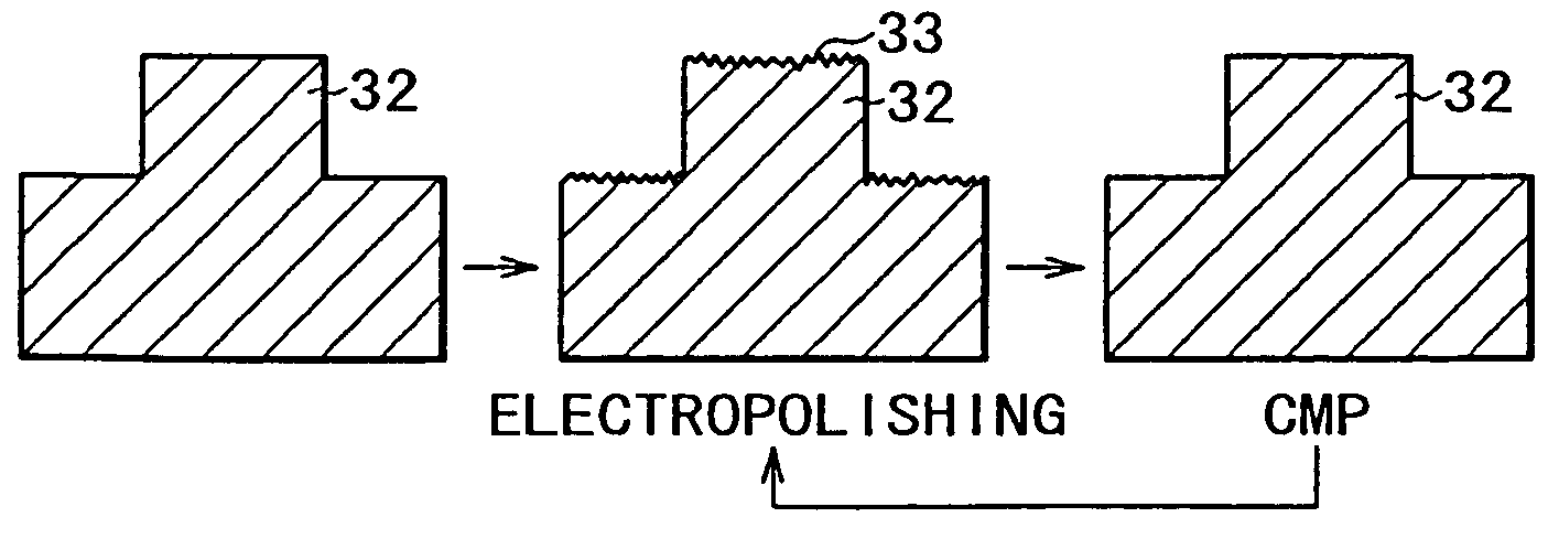
a technology of electropolishing and electropolishing method, which is applied in the direction of electrical apparatus, metal-working apparatus, electrochemical machining apparatus, etc., can solve the problems of copper film forming an unstable surface, poor surface smoothness, and difficulty in determining an accurate end point, so as to achieve satisfactory polished surface, less film peeling, and less scratches

Inactive Publication Date: 2007-08-14
SONY CORP
View PDF8 Cites 5 Cited by
  • Summary
  • Abstract
  • Description
  • Claims
  • Application Information

AI Technical Summary

Benefits of technology

[0012]According to the first polishing method, since a characteristic feature of a current waveform obtainable in the electropolishing is used to determine the electropolishing end point of the metal film on the basis of the change of the current waveform resulting from electropolishing the metal film, the electropolishing end point can be determined accurately. In a case of forming copper trench interconnections, the copper trench interconnections are normally connected together through interconnections, elements and the like that are formed in a lower layer. For this reason, even if the electropolishing is advanced with a result that insular-shaped copper film portions are left behind, each insular-shaped copper film portion left behind is placed in an electrically connected state through the interconnections, the elements and the like that are formed in the lower layer, so that a current applied in the electropolishing changes continuously. Then, when the electropolishing is further advanced up to a stage that a substrate of the copper film begins to be exposed to the outside, the current applied in the electropolishing sharply drops in the shape of a characteristic curve to a polish time, because of a sharp rise of a resistance of an electropolished film (the copper film). Thus, the electropolishing end point is determined accurately on the basis of a change of a current-time curve such as a value obtained by differentiating the current-time curve, for instance. Accordingly, the metal film is prevented from being electropolished insufficiently or to excess, with the consequence that desired trench interconnections can be formed.
[0021]According to the electropolishing apparatus of the present invention, since the electropolishing apparatus comprises the current detector for detecting the current waveform resulting from electropolishing the metal film, and the end point determination part for determining the electropolishing end point of the metal film on the basis of the change of the current detected with the current detector, the electropolishing end point can be detected accurately in the same manner as described in the polishing method of the present invention.

Problems solved by technology

Thus, there is a narrow margin of detection of the end point when a determination on the end point is made by a time management, so that the electropolishing still presents problems such as a disappearance of micro interconnections and a presence of macro interconnection remains.
Further, a mere conjecture on a quantity of removed copper from a cumulative value of integrating currents finds difficulty in determining an accurate end point, because of a local resistance change attributable to a concentration of currents, in addition to a fact that a current value in the end point is far smaller than that at a time when a whole surface was covered with copper.
As a result, the following problems occur.
That is, (1) a polished surface of the copper film constitutes an unstable surface having a poor surface smoothness, (2) there is provided an insufficient interconnection sectional area attributable to a recessed copper interconnection surface as a result of overpolish of copper filled in a trench interconnection portion, (3) a dishing occurs, (4) an erosion occurs and the like.
A local non-uniformity caused by the presence of copper remains, the overpolish of the copper and the like as described above produces short circuit failure and / or open circuit failures of interconnections.
In addition, variations of electropolishing conditions depending on an extreme change of an anode current density, as well as a deviation from bright electropolishing conditions, produce a poor surface such as a rough surface.

Method used


Image

  • Polishing method and electropolishing apparatus
  • Polishing method and electropolishing apparatus
  • Polishing method and electropolishing apparatus

Examples


Embodiment Construction

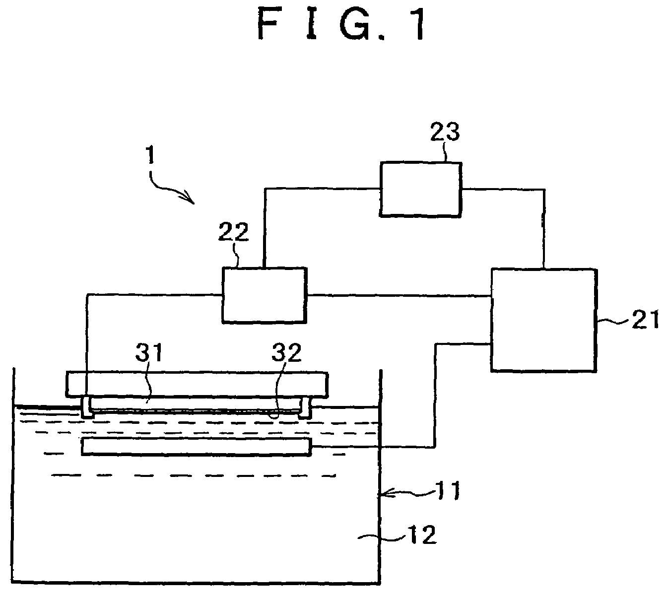
[0030]A preferred embodiment of an electropolishing apparatus according to the present invention will now be described with reference to a schematic view of FIG. 1.

[0031]As shown in FIG. 1, an electropolishing apparatus 1 comprises an electropolishing chamber 11 in which an electropolishing solution 12 is reserved. A wafer holder (not shown) is installed in the electropolishing chamber 11 such that a metal film 32 formed on a surface of a wafer 31 is immersed in the electropolishing solution 12. In addition, the electropolishing apparatus 1 also comprises a power supply 21 that a cathode is connected to the wafer 31 and an anode is connected to the electropolishing solution 12. A current detector 22 for detecting a current that flows between the power supply 21 and the anode or the cathode is connected to the power supply 21 and the cathode or anode. An end point determination part 23 for determining an electropolishing end point of the metal film 32 on the basis of a change of a cu...


PUM

PropertyMeasurementUnit
dielectric constantaaaaaaaaaa
thicknessaaaaaaaaaa
current densityaaaaaaaaaa

Abstract

A polishing method for electropolishing a metal film formed on a wafer surface so as to fill concave portions formed on the wafer surface comprises a step of determining an electropolishing end point of the metal film on the basis of a change of a current waveform resulting from electropolishing the metal film. An electropolishing apparatus comprising a current detector for detecting a current waveform resulting from electropolishing a metal film and an end point determination part for determining an electropolishing end point of the metal film on the basis of the change of a current detected with the current detector is used to realize the polishing method.

Description

CROSS REFERENCES TO RELATED APPLICATIONS[0001]The present application is a divisional of U.S. application Ser. No. 10 / 304,174, filed Nov. 26, 2002 now U.S. Pat. No. 7,156,975, which claims priority to Japanese Patent Application No. JP2001-366341, filed Nov. 30, 2001. The present application claims priority to this previously filed application. The subject matter of application Ser. No. 10 / 304,174, is incorporated herein by reference.BACKGROUND OF THE INVENTION[0002]1. Field of the Invention[0003]This invention relates to a polishing method and an electropolishing apparatus, and more specifically, a polishing method for accurately determining an end point in an electropolishing required for a case of forming embedded wirings by planarization of concave and convex portions of a copper-plated film surface with a process of forming copper interconnections, a polishing method for polishing by alternating the electropolishing with a chemical mechanical polishing repeatedly, and an electr...

Claims


Application Information

Patent Timeline
Patent Type & Authority Patents(United States)
IPC IPC(8): C25F3/22B23H3/00B23H3/02B23H5/06B24B1/00B23H5/08B24B37/00B24B37/013B24B49/04B24B49/10C25F3/16H01L21/304H01L21/3063H01L21/321H01L21/768
CPCB24B37/013B24B49/04B24B49/10
Inventor SATO, SHUZONOGAMI, TAKESHIYASUDA, ZENYAISHIHARA, MASAO
Owner SONY CORP
Why Eureka
Try Eureka