
LSI design method

a design method and integrated circuit technology, applied in the direction of logic circuit coupling/interface arrangement, pulse technique, instruments, etc., can solve the problems of increasing difficulty in timing convergence, numerous repetition of layout design and verification, etc., and achieve the effect of shortening the tim

Inactive Publication Date: 2007-08-14
SOCIONEXT INC
View PDF12 Cites 6 Cited by
  • Summary
  • Abstract
  • Description
  • Claims
  • Application Information

AI Technical Summary

Benefits of technology

[0012]In consideration of the above described problems, an object of the present invention is to estimate an uncertain amount of timing margin in response to a series of items in the early design stage of a semiconductor integrated circuit, define an uncertainty of timing margin in response to the item of which an influence on timing is indeterminable in each design process and accordingly proceed with the design, thereby shortening the time to pass a verification for sign-off at the end of a design process.

Problems solved by technology

In recent years, the design of a semiconductor integrated circuit is required for consideration of influences by an on-chip variation and a cross-talk, besides LSI for use in high speed operations, a convergence of timing has been increasingly difficult.
Since relationships among clock tree structure, layout process and sign-off condition have not been taken into consideration in establishing the timing margin, the last sign-off verification has been faced with a timing convergence problem, resulting in a numerous repetition of the layout design and the verification.
Besides, since the conventional establishing method for timing margin has not taken a condition of a product specification into consideration, thus precluding a timing margin optimization in accordance with an applicable product specification or a reestablishment of margin even if each process is faced with a problem in timing convergence.
Such has been the problem.
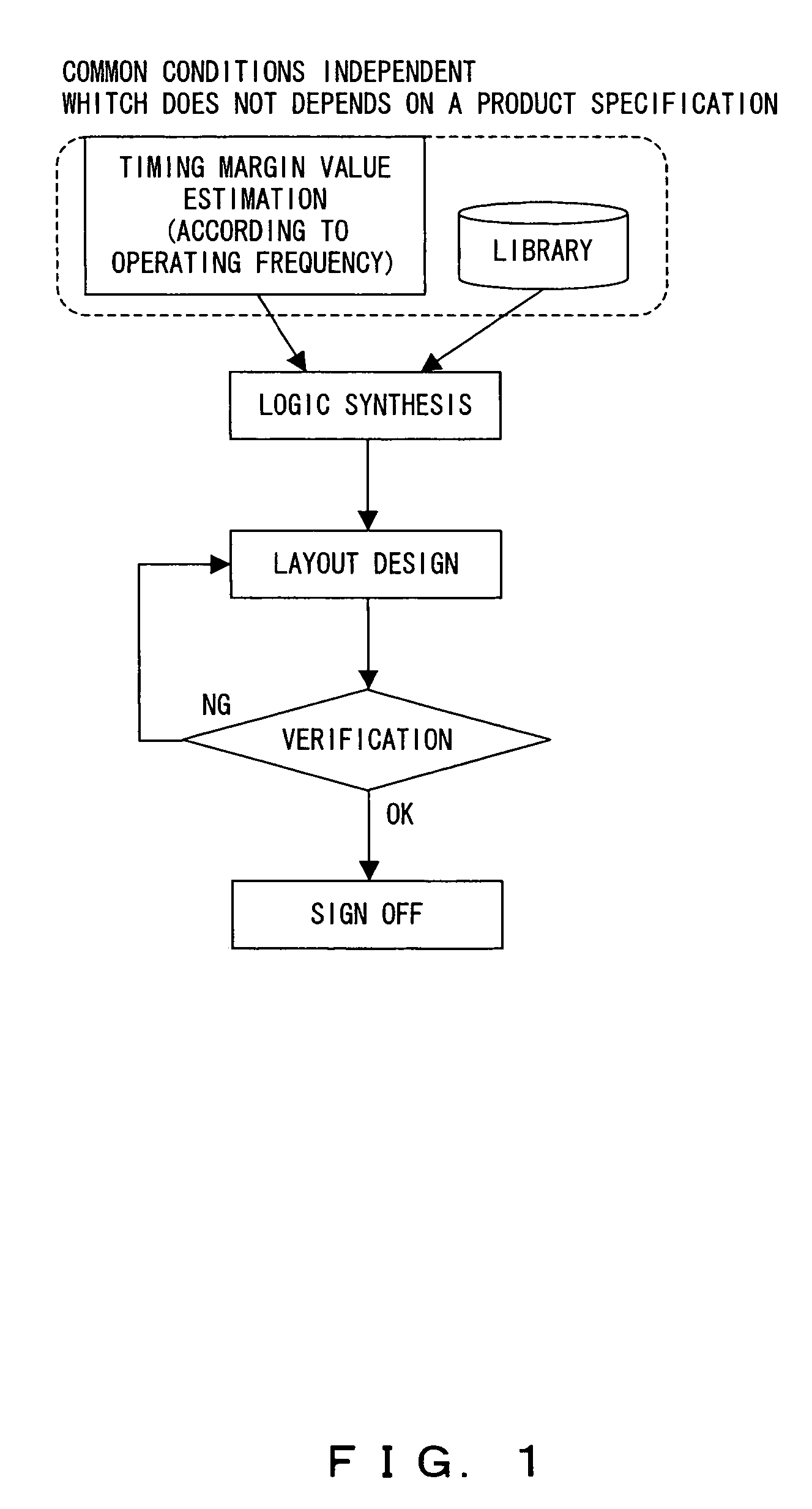
The technique disclosed in the document above, however, the timing margin is defined only in accordance with the operating frequency, therefore the method has been faced with a problem of precluding an adoption of this method if the customer requirement of operating frequency cannot be changed and an applicability of such timing margin common to all the design processes.

Method used


Image

  • LSI design method
  • LSI design method
  • LSI design method

Examples


Embodiment Construction

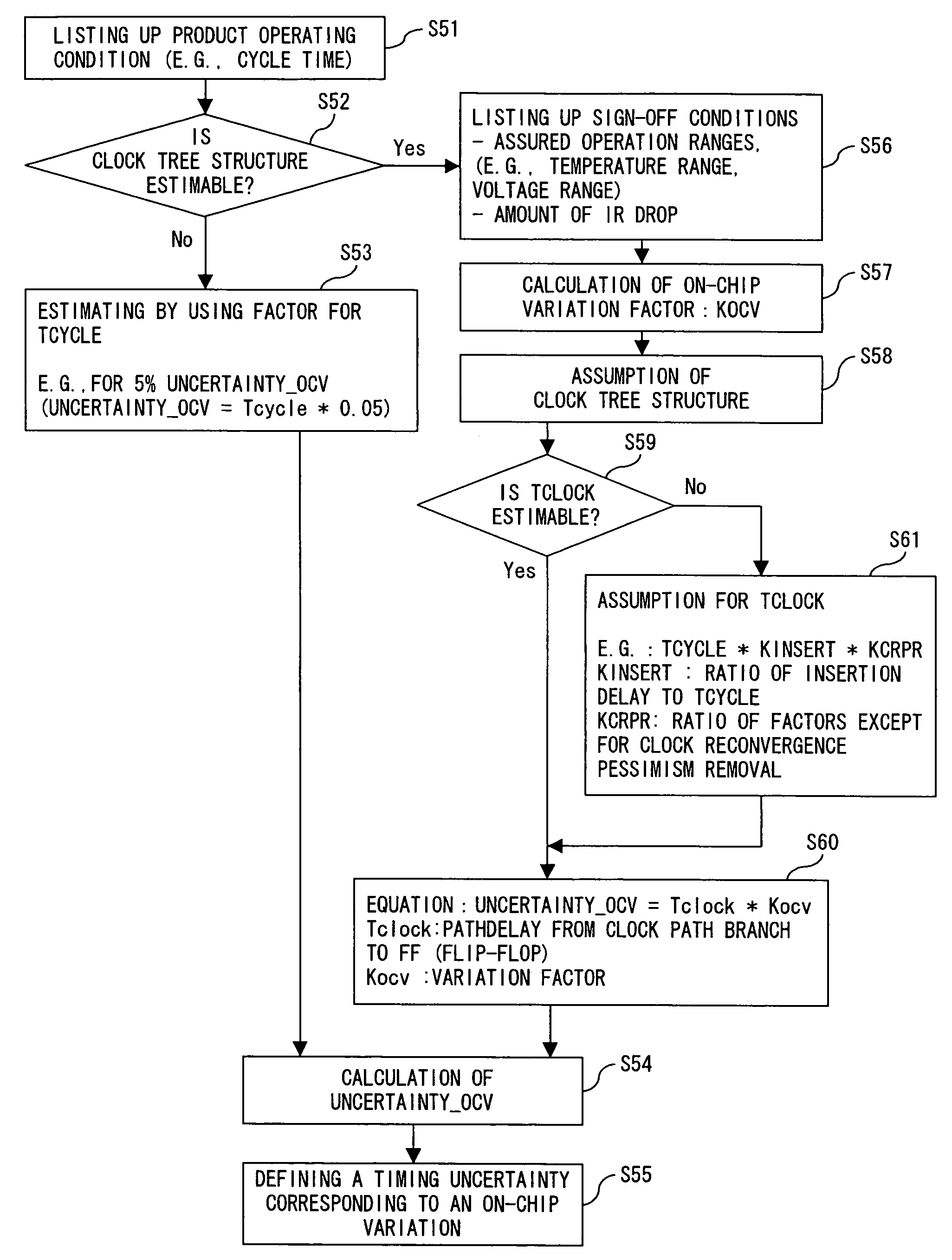
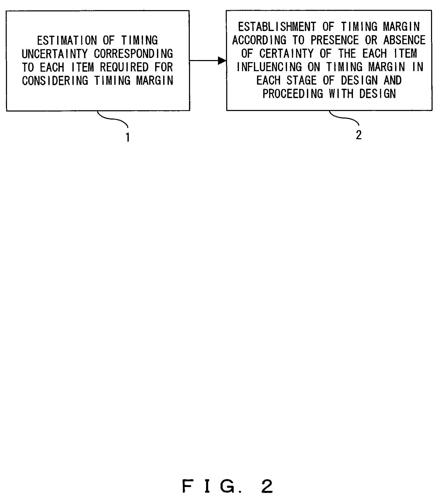
[0026]FIG. 2 shows a fundamental functional block chart of an LSI design method according to the present invention. In FIG. 2, first, step 1 estimates the timing uncertainty brought by the uncertain influences given by every item that has to be considered according to the establishment of the timing margin in an early stage of LSI design. And step 2 establishes a timing margin in each design stage of the LSI design based on the estimation result of the timing uncertainty, depending on whether or not an influence of the each item on timing has been determined. Then designs of each stage are carried out accordingly. In the present embodiment according to the invention, a timing uncertainty can also be estimated based on a condition of a product specification, an operating condition and a sign-off condition of an LSI in the step of the timing uncertainty estimation 1.

[0027]Also, in the estimation of a timing uncertainty influenced by a “Clock Skew” as one of items required for consider...


PUM


Abstract

An LSI design method according to the present invention is to estimate a timing uncertainty in an early stage of design for each item of which an influence on timing is uncertain among respective items requiring consideration relating to establishment of timing; and define a timing margin in each design stage by using the timing uncertainty estimation result depending on whether or not an influence of the each item on timing has been determined, followed by proceeding with the design in the respective design stages accordingly. As such, according to the present invention, a timing uncertainty is estimated in an early stage of LSI design, followed by proceeding with the design by using the timing uncertainty as required.

Description

CROSS-REFERENCE TO RELATED APPLICATIONS[0001]This application is based upon and claims the benefit of priority from the prior Japanese Patent Application No. 2004-174722, filed in Jun. 11, 2004, the entire contents of which are incorporated herein by reference.BACKGROUND OF THE INVENTION[0002]1. Field of the Invention[0003]The present invention relates to a design method for a semiconductor integrated circuit, specifically to a design method for LSI in which an uncertain amount of timing is adjusted while eliminating factors relative to determined timings during a design process thereof.[0004]2. Description of the Related Art[0005]In recent years, the design of a semiconductor integrated circuit is required for consideration of influences by an on-chip variation and a cross-talk, besides LSI for use in high speed operations, a convergence of timing has been increasingly difficult. This makes it important to establish an uncertain amount of timing (“timing uncertainty” hereinafter) a...

Claims


Application Information

Patent Timeline
Patent Type & Authority Patents(United States)
IPC IPC(8): G06F17/50H01L21/82H03K19/00H03K19/0175
CPCG06F17/505G06F30/327
Inventor HOSONO, TOSHIKATSUYONEDA, TAKASHI
Owner SOCIONEXT INC
Learn More