Battery connector with retaining board

a battery connector and retaining board technology, applied in the direction of coupling device connection, coupling contact member, coupling device details, etc., can solve the problems of unstable prone to relative horizontal displacement and easy loosening of the soldering portion of the terminals, etc., to achieve stable electrical connection between the battery connector and the printed circuit board

Inactive Publication Date: 2007-08-21
CHENG UEI PRECISION IND CO LTD
View PDF4 Cites 11 Cited by
  • Summary
  • Abstract
  • Description
  • Claims
  • Application Information

AI Technical Summary

Benefits of technology

[0008]When the battery is pressed against the contacting portion of the terminal backward, the printed circuit board is depressesed toward the vertical cooperating wall at the same time. Moreover, the printed circuit board is retained firmly by the retaining board and the top wall. As a result, the battery connector with retaining board can avoid a relative horizontal displacement between the battery connector and the printed circuit board, and avoid the soldering portion of the terminals being loosened from the printed circuit board. Therefore, the electrical connection between the battery connector and the printed circuit board is stable.

Problems solved by technology

When the battery is horizontally depressed against the contacting portions of the terminals, a relative horizontal displacement is liable to be caused between the battery connector and the printed circuit board.
As a result, the soldering portion of the terminals is easily to be loosened from the printed circuit board: therefore, the electrical connection between the battery connector and the printed circuit board is not stable.
Such kind of loose situation also happen when the electronic device is struck.

Method used


Image

  • Battery connector with retaining board
  • Battery connector with retaining board
  • Battery connector with retaining board

Examples


Embodiment Construction

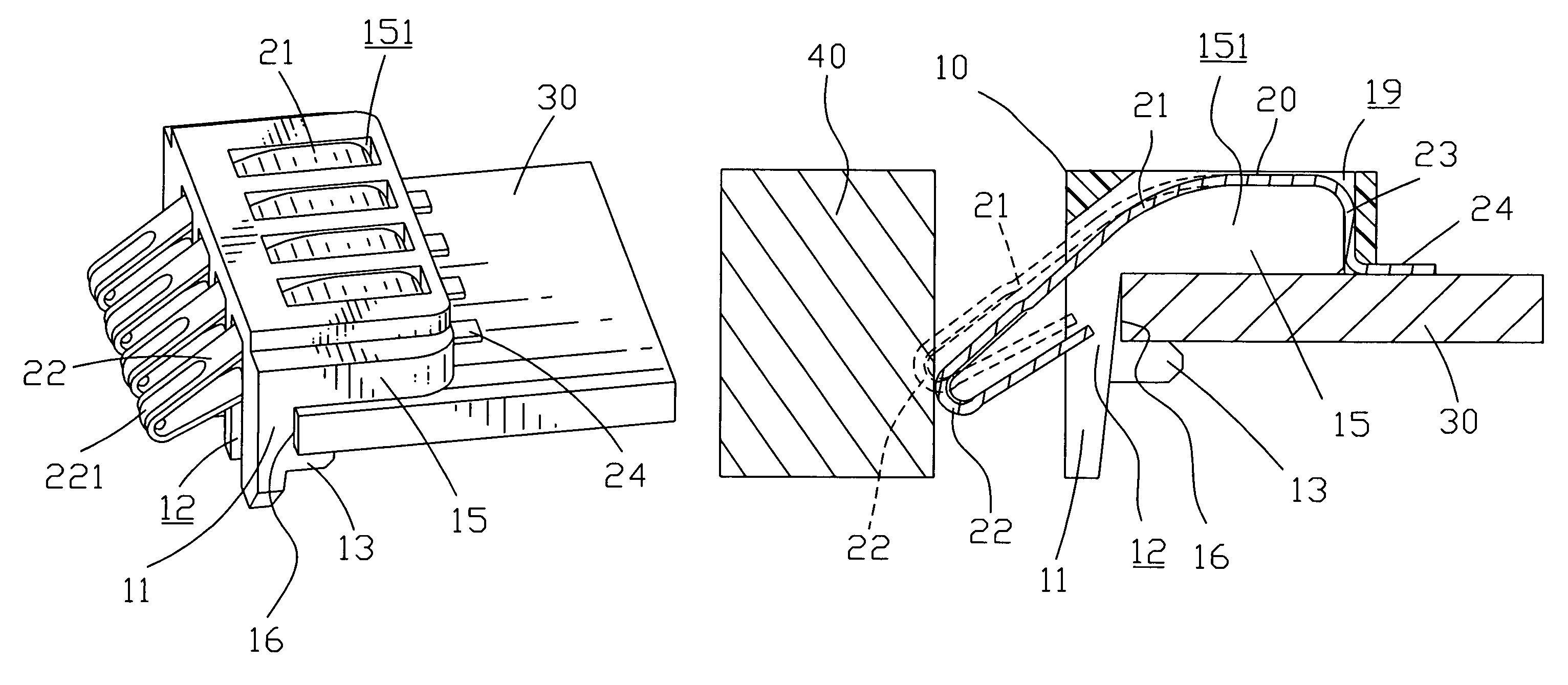
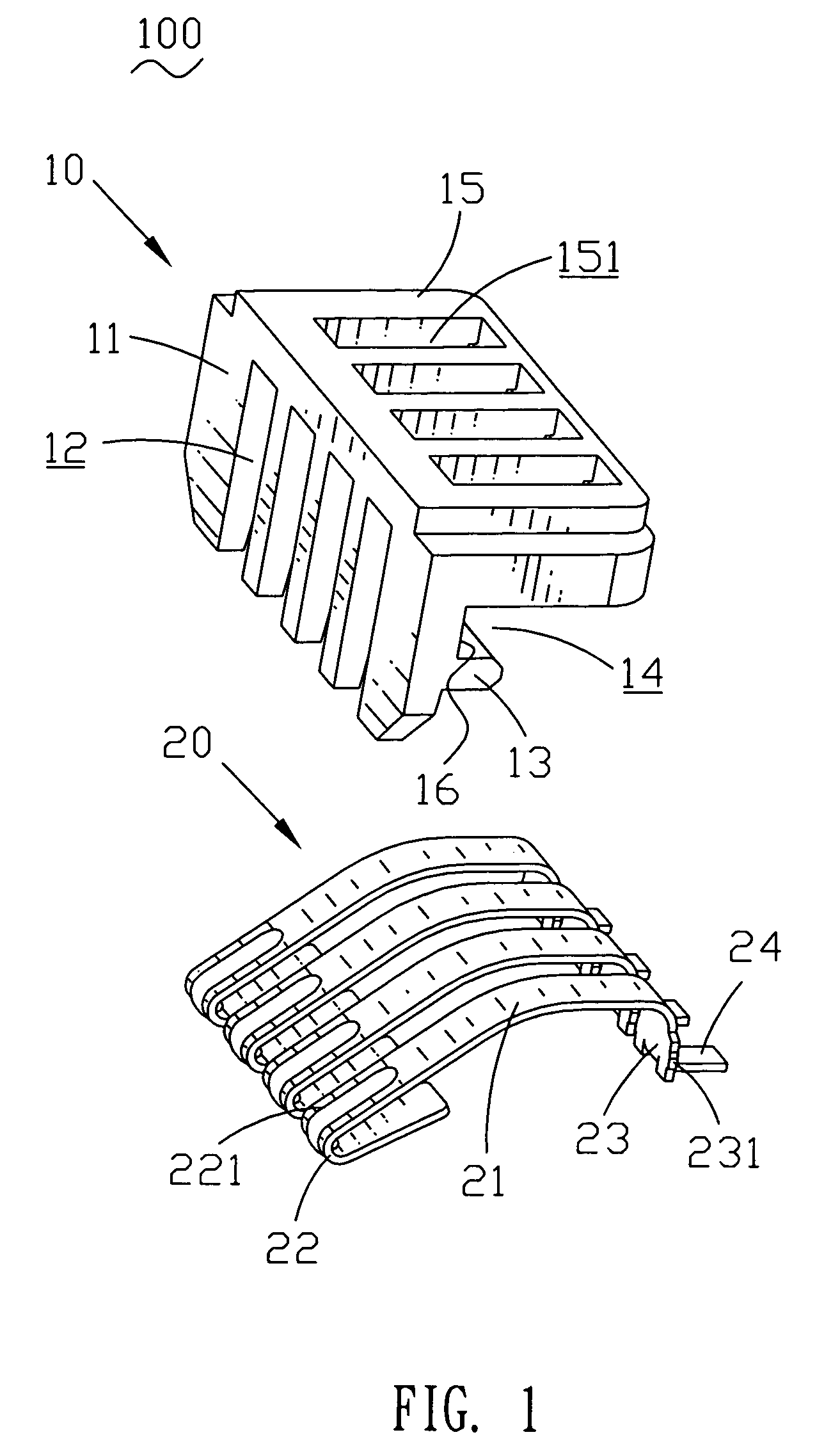
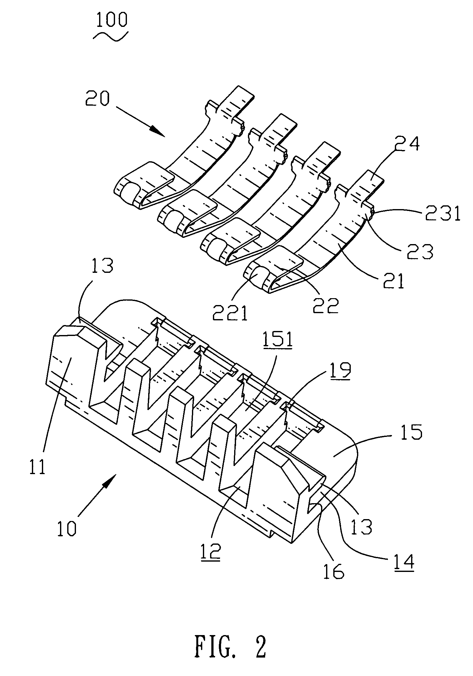
[0016]Please refer to FIGS. 1 and 2. A battery connector with retaining board 100 includes an insulating housing 10 and a plurality of terminals 20 received in the insulating housing 10.

[0017]The insulating housing 10 includes a vertical cooperating wall 11 and a top wall 15 horizontally extending backward from the top of the vertical cooperating wall 11. A plurality of receiving cavities 12 are transversally arranged through the vertical cooperating wall 11 and are parallel to each other. A retaining board 13 horizontally extends backward from the middle of the vertical cooperating wall 11, thereby, a retaining space 14 is formed between the retaining board 13 and the top wall 15. The height of the retaining space 14 is substantially equal to the thickness of a printed circuit board. A contacting side 16 is formed on the backside of the vertical cooperating wall 11 and located between the top wall 15 and the retaining board 13. A plurality of holding cavities 151 are defined throug...


PUM


Abstract

A battery connector with retaining board includes an insulating housing and a plurality of terminals received in the insulating housing. Each terminal includes a connecting portion, a contacting portion and a soldering portion. The insulating housing has a vertical cooperating wall. A top wall and a retaining board backward extend from the backside of the vertical cooperating wall, thereby a retaining space is formed therebetween. The backside of the cooperating wall defines a contacting side formed between the top wall and the retaining board. A printed circuit board is retained in the retaining space and one end of the printed circuit board is depressed against the contacting side of the insulating housing whereby a firmly engagement is between the printed circuit board and the battery connector. Therefore, an electrical connection therebetween is stable.

Description

BACKGROUND OF THE INVENTION[0001]1. Field of the Invention[0002]The present invention relates to a battery connector, and more particularly to a battery connector with retaining board.[0003]2. The Related Art[0004]A battery connector is widely used in a mobile phone or other electronic devices for electrically connecting a battery with a printed circuit board mounted in the mobile phone.[0005]FIG. 6 shows a conventional battery connector. The battery connector 1 has an insulating housing 2 and a plurality of terminals 3 received in the insulating housing 2. The insulating housing 2 is mounted on an inner printed circuit board 4 of an electronic device. Each terminal 3 includes a contacting portion 6 and a soldering portion 7. The contacting portion 6 stretches out of the cooperating wall of the insulating housing 2 and contacts a battery 5, the soldering portion 7 stretches out of the bottom of the insulating housing 2 and contacts the printed circuit board 4.[0006]However, the batt...

Claims


Application Information

Patent Timeline
Patent Type & Authority Patents(United States)
IPC IPC(8): H01R3/00
CPCH01R13/2442H01R12/7064H01R12/721H01R11/281
Inventor CHEN, CHUNG-YU
Owner CHENG UEI PRECISION IND CO LTD
Why Eureka
Try Eureka