Bicycle transmission

a transmission device and bicycle technology, applied in the direction of gearing, transportation and packaging, hoisting equipment, etc., can solve the problems of excessive cleaning of the rear derailleur, chain damage, rear derailleur dirt exposure, etc., to achieve higher ground clearance, reduce ground clearance, and improve efficiency

Active Publication Date: 2007-08-21
SHIMANO INC
View PDF20 Cites 24 Cited by
  • Summary
  • Abstract
  • Description
  • Claims
  • Application Information

AI Technical Summary

Benefits of technology

[0020]Another advantage of the present invention is that the transmission of the present invention can be constructed to weigh less than other frame mounted type transmissions and be more efficient. This transmission is more efficient than an “internal gear hub” mounted to the frame.
[0021]Another advantage of the present invention is that the transmission of the present invention provides higher ground clearance. Thus, this transmission can be geared higher without lowering ground clearance. In contrast, as the front chain wheel gets larger in a conventional derailleur type transmission, the ground clearance is reduced.

Problems solved by technology

While these type of typical transmissions work very well, these types of bicycle transmissions require the chain to be pushed or pulled in a transverse direction of the bicycle.
Over an extended period of time, this bending of the chain causes the chain to be damaged.
This exposes the rear derailleur to dirt and debris from the wheel.
Thus, the rear derailleur can become excessively dirty and stop shifting properly.
Moreover, the location of the rear derailleur is prone to being hit by objects during riding.
Also, the rear derailleur is often damaged if the bicycle falls over.
Thus, in these conventional derailleur type transmissions that are at least partially disposed at the rear wheel, these conventional derailleur type transmissions are shaken and swung up and down violently with the rear wheel.
This can significantly decrease the operation and durability of the drive train.
Further, conventional derailleur type transmission has considerably more unsprung weight than a rear wheel without derailleur type transmission mounted thereto.

Method used


Image

  • Bicycle transmission
  • Bicycle transmission
  • Bicycle transmission

Examples


Embodiment Construction

[0033]Selected embodiments of the present invention will now be explained with reference to the drawings. It will be apparent to those skilled in the art from this disclosure that the following descriptions of the embodiments of the present invention are provided for illustration only and not for the purpose of limiting the invention as defined by the appended claims and their equivalents.

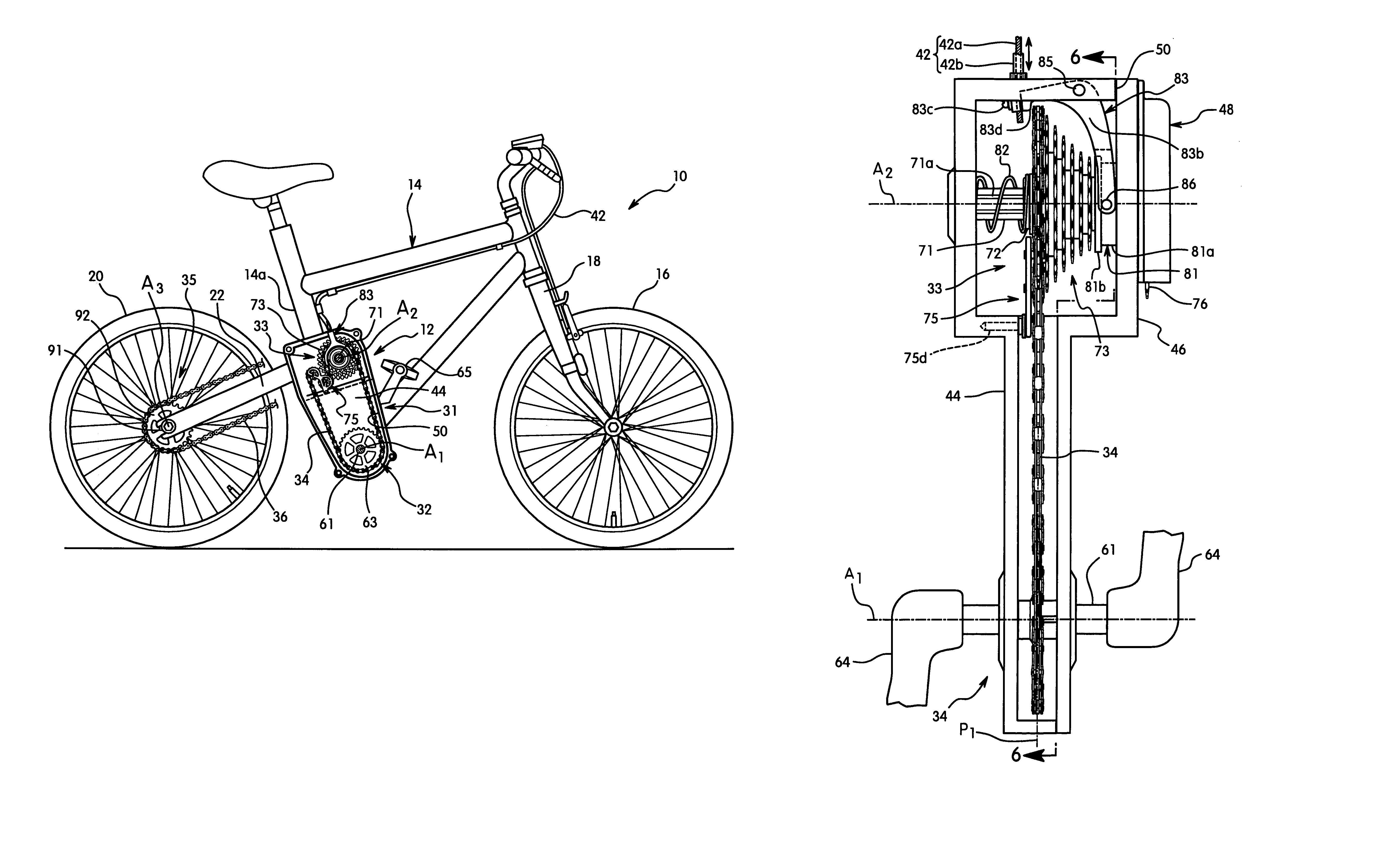
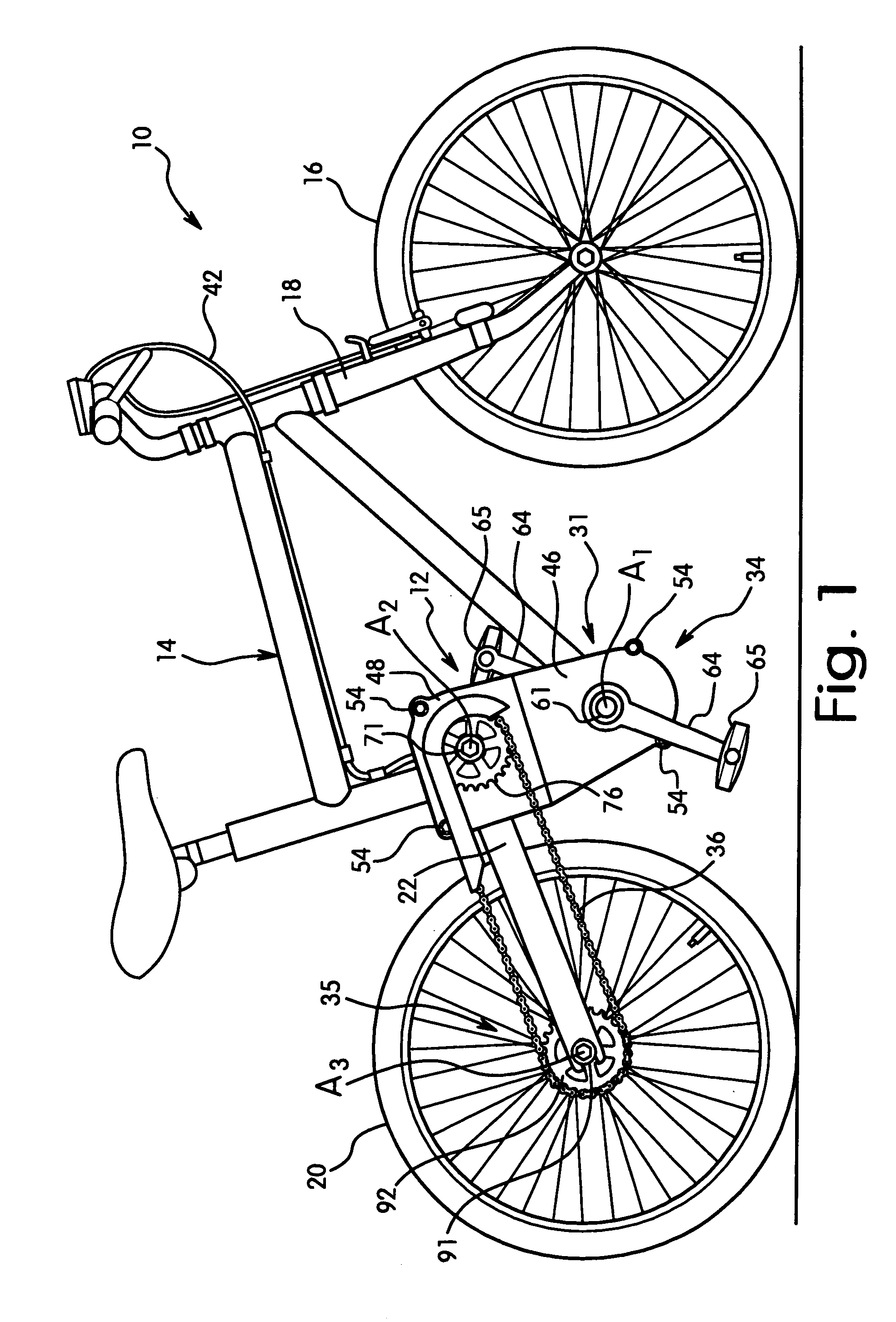
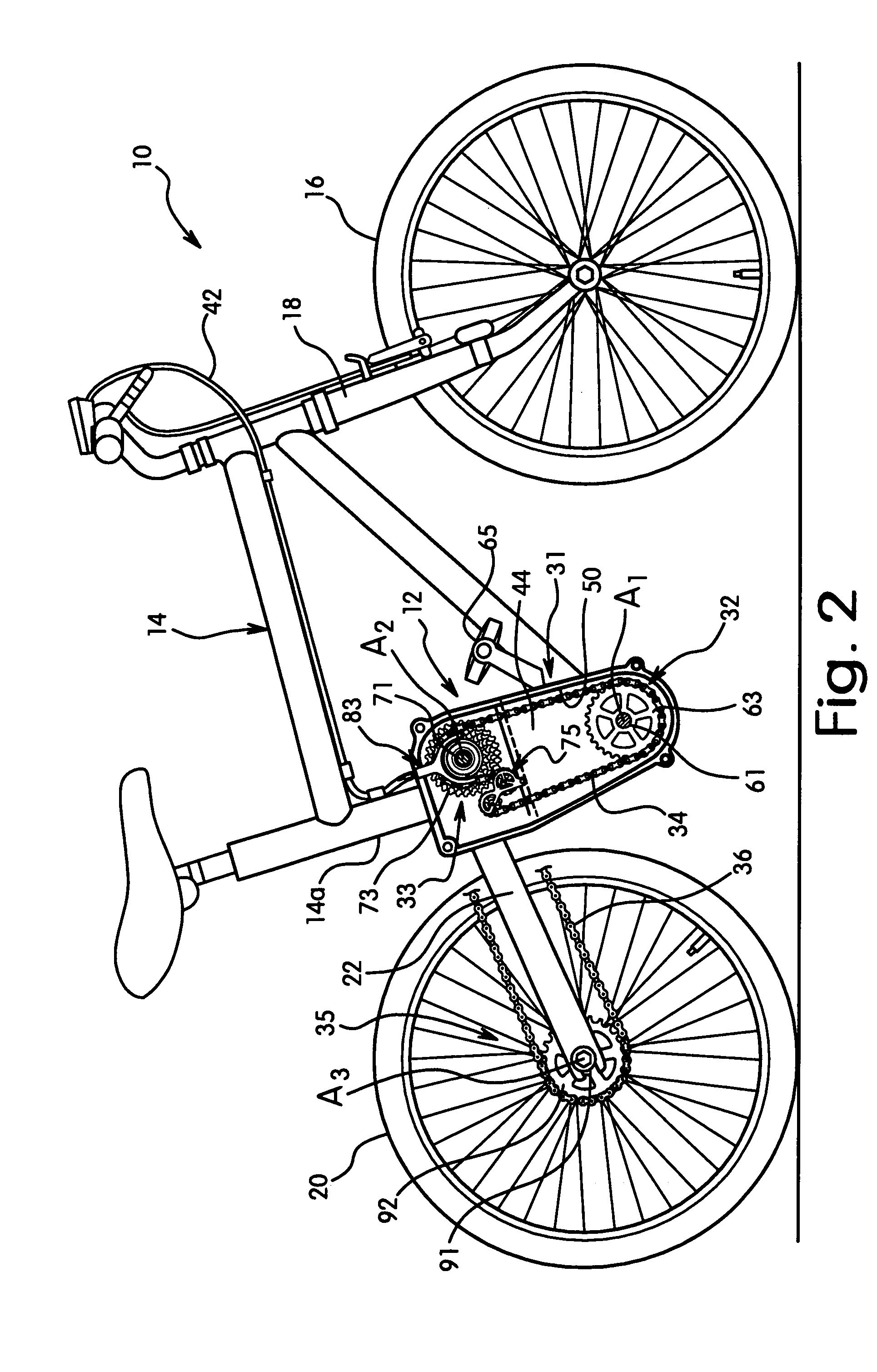
[0034]Referring initially to FIGS. 1 and 2, a bicycle 10 is illustrated that is equipped with a bicycle transmission 12 in accordance with a first embodiment of the present invention. The bicycle 10 further includes a bicycle frame 14 having a front wheel 16 rotatably coupled to the front fork 18 of the frame 14 and a rear wheel 20 rotatably coupled to a rear fork 22 of the frame 14. Since these parts of bicycle 10 are well known in the art, these parts will not be discussed or illustrated in detail herein, except as they are modified to be used in conjunction with the present invention. Moreover, ...


PUM


Abstract

A bicycle transmission is configured and arranged to improve the durability of the transmission. The transmission basically has a transmission operating device, a support structure, a front input section, an intermediate transmission and a rear output section. The transmission operating device operates the intermediate transmission to change the gear ratio between the front input section and the rear output section. The intermediate transmission has a plurality of drive members arranged to move in the axial direction on an intermediate drive axle in response to its pivotal movement shifting structure. An endless drive member is operatively coupled between a rotatable driving member of the front input section and one of the intermediate drive members. The endless drive member remains substantially in a single plane during shifting of the drive members on the intermediate drive axle.

Description

BACKGROUND OF THE INVENTION[0001]1. Field of the Invention[0002]This invention generally relates to a bicycle transmission. More specifically, the present invention relates to a bicycle transmission in which an endless drive member or chain remains substantially in a single plane.[0003]2. Background Information[0004]Bicycling is becoming an increasingly more popular form of recreation as well as a means of transportation. Moreover, bicycling has become a very popular competitive sport for both amateurs and professionals. Whether the bicycle is used for recreation, transportation or competition, the bicycle industry is constantly improving the various components of the bicycle. One component that has been extensively redesigned is the bicycle transmission.[0005]One of the most popular types of bicycle transmissions utilizes a plurality of sprockets mounted on the hub of a rear wheel. A rear derailleur is utilized to shift a chain between adjacent sprockets. The rear derailleur is typ...

Claims


Application Information

Patent Timeline
Patent Type & Authority Patents(United States)
IPC IPC(8): B62M9/14F16H63/02F16H9/06B62M9/10B62M9/04B62M9/131B62M9/16B62M11/06
CPCB62M9/14
Inventor THOMASBERG, PAUL
Owner SHIMANO INC
Why Eureka
Try Eureka