Angiographic fluid control system

a fluid control system and fluid technology, applied in the field of fluid control systems, can solve the problems of damage or malfunction of the transducer, difficult grasping and manipulating of small handles, and a considerable degree of training to learn how to properly operate one of the prior art manifolds, etc., and achieve the effect of improving pressure reading

Inactive Publication Date: 2007-08-21
MEDLINE INDUSTRIES
View PDF18 Cites 93 Cited by
  • Summary
  • Abstract
  • Description
  • Claims
  • Application Information

AI Technical Summary

Benefits of technology

[0021]In another refinement, a fluid control system is provided whereby a pressure transducer is coupled directly to or closely adjacent to the proximal end of the catheter for improved pressure reading.

Problems solved by technology

Because a physician is required to manipulate a number of stopcock valves during a procedure to achieve a desired flow path to or from the catheter, it takes a considerable degree of training to learn how to properly operate one of the prior art manifolds.
Further, because it is not immediately evident from looking at the manifold which way the fluid is flowing, it is easy to make an improper connection resulting in a high-pressure fluid being applied to a pressure transducer, causing damage to or malfunction of the transducer.
However, the small handles can be difficult to grasp and manipulate.
Another problem associated with currently available manifolds is the use of a single output conduit which is connected to the catheter.
As a result, contrast can often be wasted because there is no way to “save” the contrast once it has been injected into the manifold.
Further, if waste material is drawn into the manifold, saline is wasted as the manifold is flushed.
Further, it is time consuming to flush the manifold between functions.
Finally, because currently available manifolds are equipped with a pressure transducer, adjacent the injector, which may be a syringe or power injector, the pressure readings are compromised due to waveform dampening that occurs in the manifold.
As a result of the waveforms having to travel through this extensive length of conduit, substantial dampening occurs, thereby compromising the pressure readings.

Method used


Image

  • Angiographic fluid control system
  • Angiographic fluid control system

Examples


Embodiment Construction

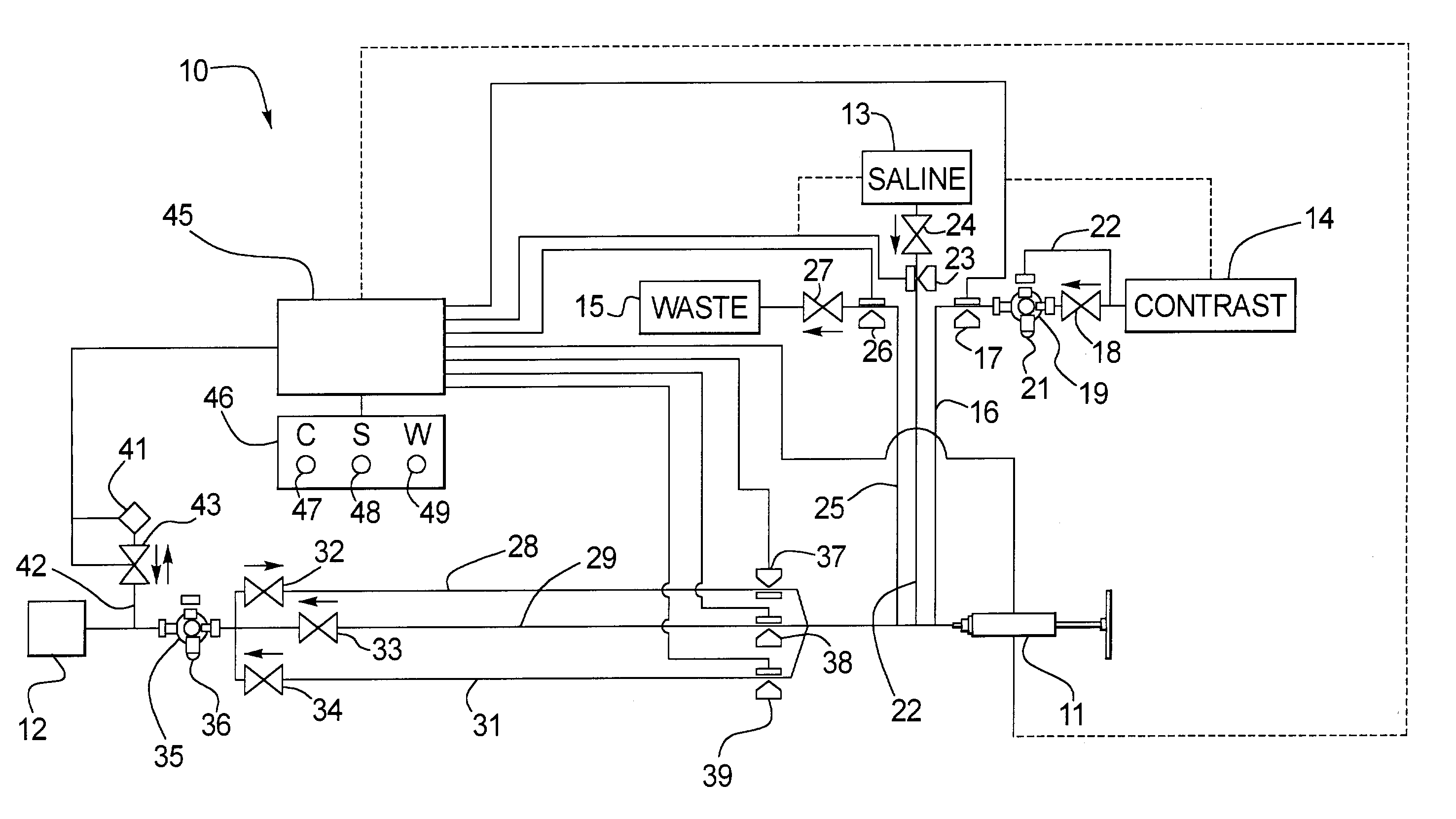
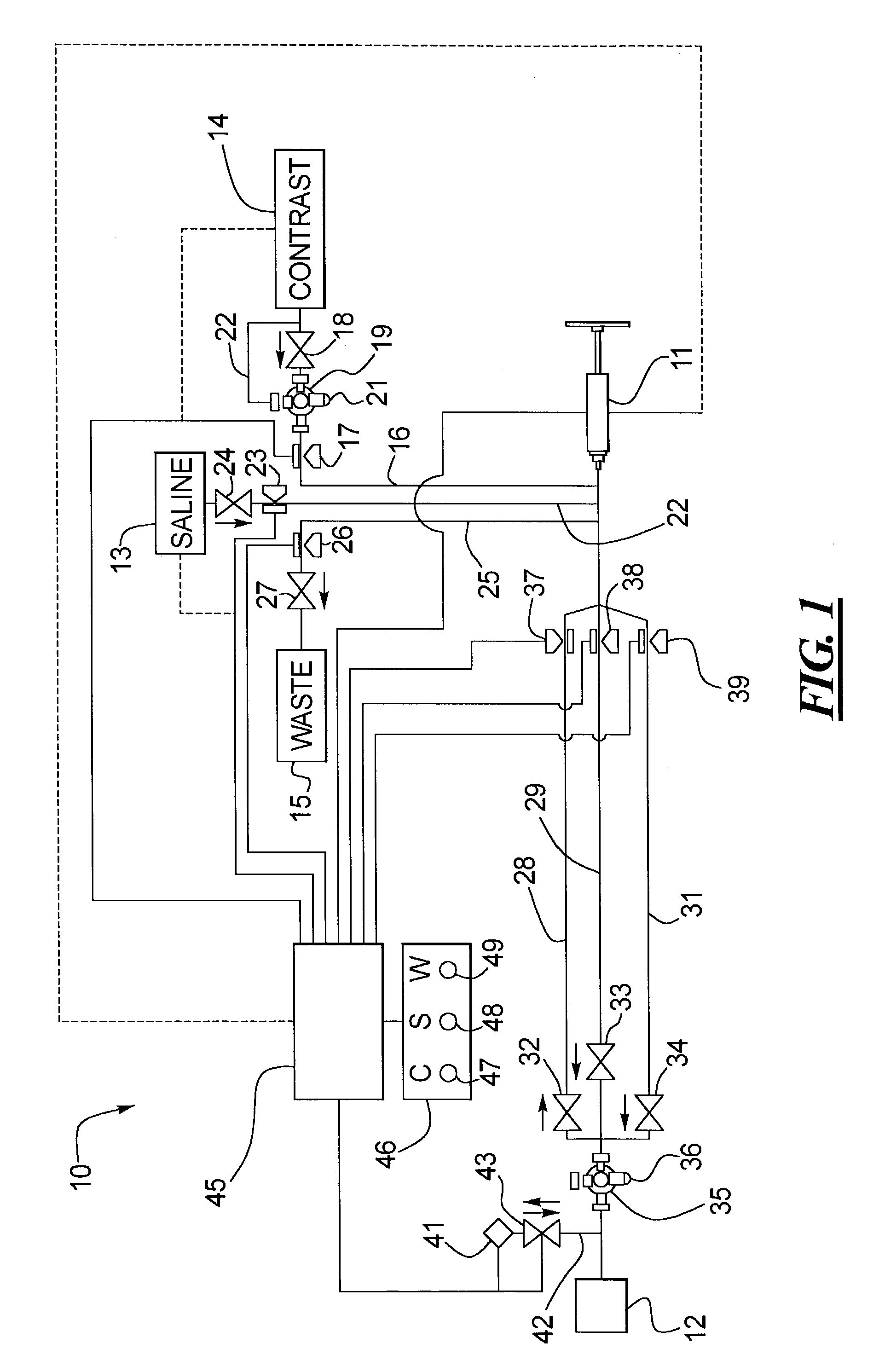
[0024]A fluid control system 10 includes an injector 11 and a catheter shown schematically at 12. Two primary fluids are injected into the catheter-saline from the saline supply 13 and contrast from the contrast supply 14. In the embodiment 10 shown in FIG. 1, waste fluid is also drawn in from the catheter 12 and deposited in the waste dump 15.

[0025]The contrast supply 14 is coupled to a contrast supply line 16. The contrast supply line 16 passes through a contrast input pinch valve 17. The contrast supply line 16 may also pass through a one-way check valve 18, the function of which will be described later. Similarly, to facilitate the injection of medicaments into the system, a stopcock 19 is disposed in the contrast input line 16. The stopcock 19 preferably includes an injection port 21. A bypass line 22 may also be provided to bypass the one-way check valve 18. The bypass line 22 can be used to save unneeded clean contrast solution by injecting it back into the contrast supply 14...


PUM


Abstract

An automated fluid control system for controlling fluid flow between a catheter, a saline supply, a contrast supply and an injector is disclosed. Pinch valves are provided in the saline input and output lines and contrast input and output lines. A controller is linked to the pinch valves to sequentially open and close the pinch valves during functions which include contrast injection and saline injection.

Description

CROSS-REFERENCE TO RELATED APPLICATION[0001]This application claims the benefit under 35 U.S.C. § 119(e) of U.S. provisional patent application Ser. No. 60 / 326,940 filed Oct. 4, 2001, the disclosure of which is incorporated herein by reference.TECHNICAL FIELD[0002]A fluid control system is disclosed for controlling fluid flow in an angiographic apparatus. More specifically, a fluid control system is disclosed for controlling fluid flow between a catheter, a saline supply, a waste dump, a contrast supply and an injector.BACKGROUND OF THE RELATED ART[0003]Various medical procedures involve the introduction of fluids into the body of a patient using a catheter. When a series of different fluids are to be administered, it is often necessary to flush one fluid from the catheter before the next fluid is administered. For example, during angioplasty, the catheter is often flushed with saline before and / or after the addition of contrast solution. Further, it is also necessary to purge any i...

Claims


Application Information

Patent Timeline
Patent Type & Authority Patents(United States)
IPC IPC(8): A61M5/00A61M1/00A61M31/00A61M37/00A61M5/145A61M5/168
CPCA61M5/007A61M5/16827A61M5/14546
Inventor HOUDE, ERIC
Owner MEDLINE INDUSTRIES
Why Eureka
Try Eureka