Method and apparatus for magnetic separation of particles

a technology of magnetic separation and particle, applied in the field of magnetic separation of particles, can solve the problem of still required magnets

Inactive Publication Date: 2007-08-21
DEXTER MAGNETIC TECH
View PDF12 Cites 5 Cited by
  • Summary
  • Abstract
  • Description
  • Claims
  • Application Information

AI Technical Summary

Problems solved by technology

However, magnets are still required to separate the target particles from the solution contained in micro-plates.

Method used


Image

  • Method and apparatus for magnetic separation of particles
  • Method and apparatus for magnetic separation of particles
  • Method and apparatus for magnetic separation of particles

Examples


Embodiment Construction

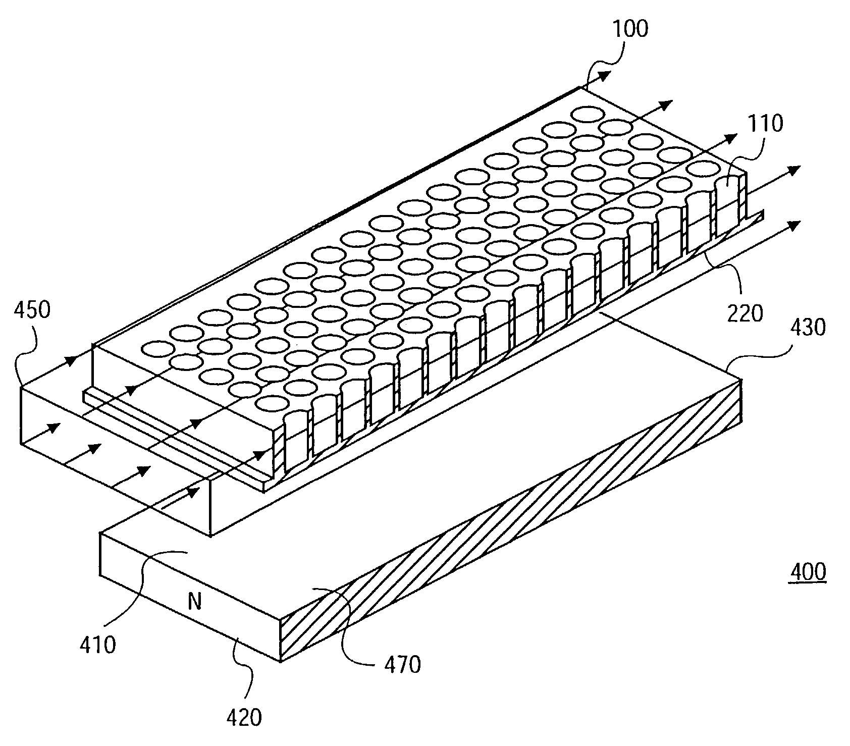
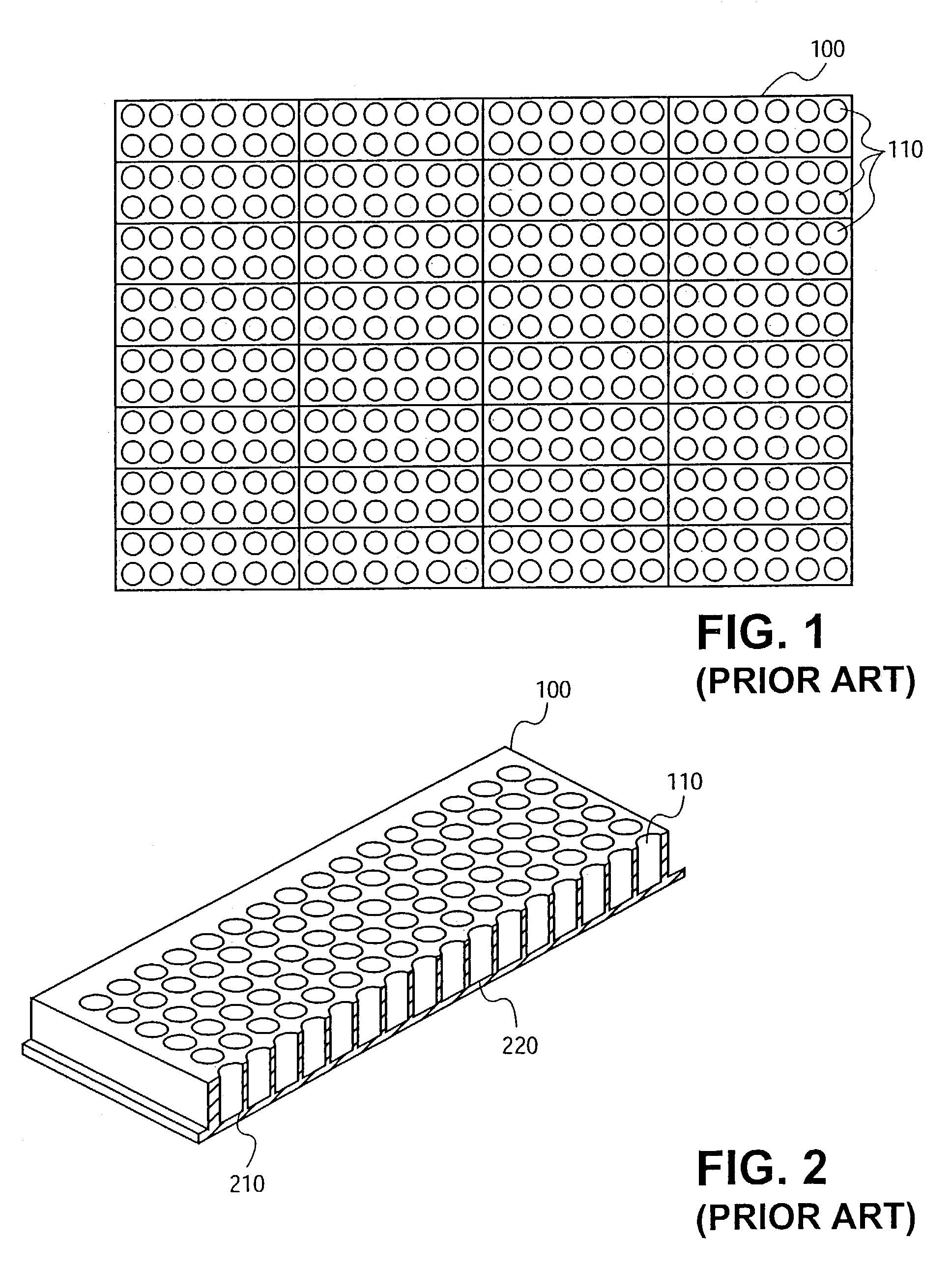
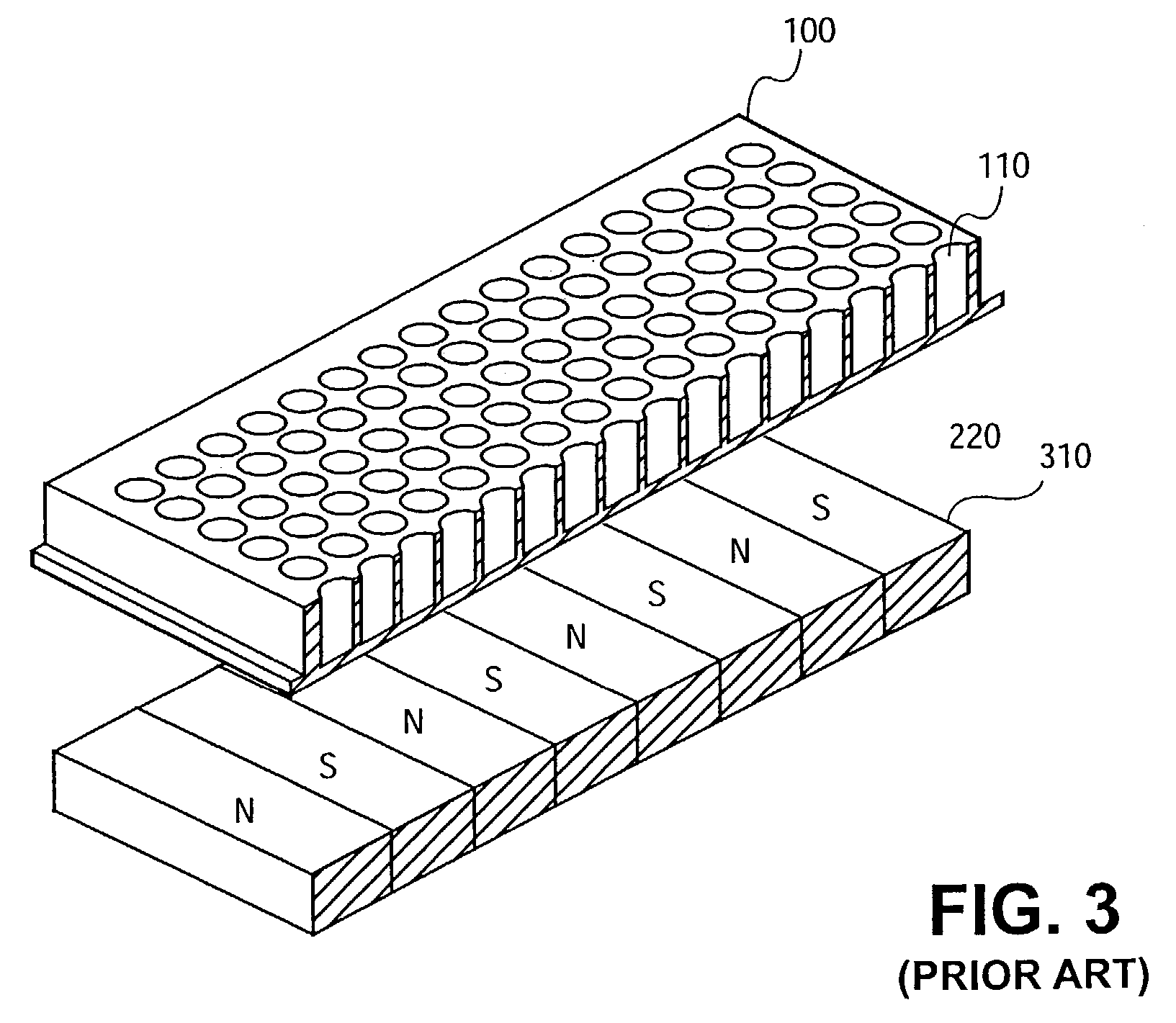
[0021]Described is a method and apparatus for bead separation. In one embodiment, the method and apparatus causes beads within a fluid container (e.g., the wells of a micro-plate) to uniformly distribute about the base of the container to produce a “flat” profile. In addition, the method an apparatus causes the “flat” profile to form in an expedient manner, significantly increasing the throughput for bead separation.

[0022]In the following description, various aspects of the present invention will be described. However, it will be apparent to those skilled in the art that the present invention may be practiced with only some or all aspects of the present invention. For purposes of explanation, specific numbers, materials and configurations are set forth in order to provide a thorough understanding of the present invention. However, it will also be apparent to one skilled in the art that the present invention may be practiced without the specific details. In other instances, well-know...


PUM

PropertyMeasurementUnit
angleaaaaaaaaaa
magnetic fieldaaaaaaaaaa
magneticaaaaaaaaaa

Abstract

A magnetic circuit is shaped to generate an essentially uniform magnetic field parallel across the length of a container, and an essentially uniform magnetic field gradient along the length of the container as well. The dot product of the magnetic field and magnetic field gradient, known as the relative force density, is substantially uniform over the entire container, thereby causing particles to uniformly separate throughout the container.

Description

[0001]This application claims the benefit of provisional application No. 60 / 350,865, filed Jan. 22, 2002.FIELD OF INVENTION[0002]The present invention generally relates to the use of magnetic fields. More specifically, the present invention relates to the magnetic separation of particles in a solution.BACKGROUND OF THE INVENTION[0003]The use of high gradient magnetic fields for the separation of particles is commonplace in the fields of biology, biotechnology, and other bio-medical fields. Target particles, comprising entities such as proteins and the like, may be separated from a solution by a technique known as magnetic separation.[0004]In general, magnetic separation of specifically sought after biological entities involves coating small magnetically susceptible paramagnetic, super paramagnetic, or ferromagnetic, materials with a chemical-specific substance (e.g., a ligand that is known to chemically bond with target entities). These coated materials are referred to hereinafter a...

Claims


Application Information

Patent Timeline
Patent Type & Authority Patents(United States)
IPC IPC(8): B01D21/26B03C1/02G01N33/53B03C1/035G01N35/00G01N35/02
CPCB03C1/035G01N35/0098G01N35/028
Inventor RAS, CHRISTOPHER A.HATCH, GARETH P.
Owner DEXTER MAGNETIC TECH
Why Eureka
Try Eureka