Detector module

a technology of detector module and connector housing, which is applied in the field of detector module, can solve the problems of increasing the space requirement of the plug-in connector housing and the relationship, and achieve the effects of reliable electrical connection, improved quality, and improved performan

Inactive Publication Date: 2007-08-21
SIEMENS AG
View PDF25 Cites 13 Cited by
  • Summary
  • Abstract
  • Description
  • Claims
  • Application Information

AI Technical Summary

Benefits of technology

[0008]According to an embodiment of the invention, the first contact points and the second contact points are arranged in a congruent grid and are electrically connected by way of an electrical elastomer connector. The use of an electrical elastomer connector allows contact to be made with a large number of detector elements with a minimal space requirement. The plug-in connector housing which takes up a great deal of space can be avoided.
[0009]Since it is possible to obviate the electrical plug-in connectors used previously, the expensive soldering work can also be avoided. Instead of having to use a plurality of plug-in connectors when the number of detector elements increases, the electrical connection of the detector elements to the evaluation electronics can be produced by a single multipin connection. The electrical elastomer connector according to an embodiment of the invention may be extremely cost-efficient compared with the electrical plug-in connectors used previously.
[0010]In an advantageous refinement, the electrical elastomer connector may have electrically conductive structures arranged mutually parallel. Such electrically conductive structures arranged mutually parallel are expediently gold wires. The gold wires may be incorporated in a plate-like elastomer substrate. The gold wires may have a diameter of 50 micrometers. In this way, it is possible to achieve a very small distance between the gold wires and a good electrical conductivity. Spacings of less than 0.05 millimeters between the individual gold wires are possible. It is possible to achieve a large number of connection contacts within a very narrow space.
[0012]In a refinement of an embodiment of the invention, the electrical elastomer connector is held in a positioning frame between a module board holding the detector elements and the circuit board. The positioning frame is used to position the electrical elastomer connector between the module board and the circuit board, so that the electrically conductive structures of the electrical elastomer connector can be reliably connected to the contacts which need to be connected together. The positioning frame is also used to fix the elastomer connector, so that it stays in its position even in the event of vibrations or impact. The positioning frame is furthermore used as a spacer. This avoids excessive compression of the elastomer connector when the detector module is being assembled.
[0015]According to another refinement, the circuit board may carry at least one integrated circuit. This may be an application-specific integrated circuit, a so-called ASIC, in which case the spacings of the first contact points and second contact points in the grid may be from 0.2 to 0.8 millimeters, preferably from 0.3 to 0.6 millimeters. The accurate matching of the grid distribution between the module board and the circuit board permits a reliable electrical connection using the elastomer connector, in particular when the gold wires are arranged parallel in the elastomer connector.
[0016]In order to achieve an object of an embodiment, a detector is furthermore provided, in particular for an X-ray computer tomograph, which has a multiplicity of detector elements. The detector can thus accommodate future detector modules with improved quality and improved performance, so that the quality and performance of the detector will be automatically increased.

Problems solved by technology

Commercially available plug-in connectors have a limited number of contacts, however, so that it is generally possible to increase the contact number only by using a plurality of plug-in connectors.
But this leads to problems relating to exact alignment of the plugs with one another, and entails an increased space requirement for the plug-in connector housing.

Method used


Image

  • Detector module
  • Detector module
  • Detector module

Examples


Embodiment Construction

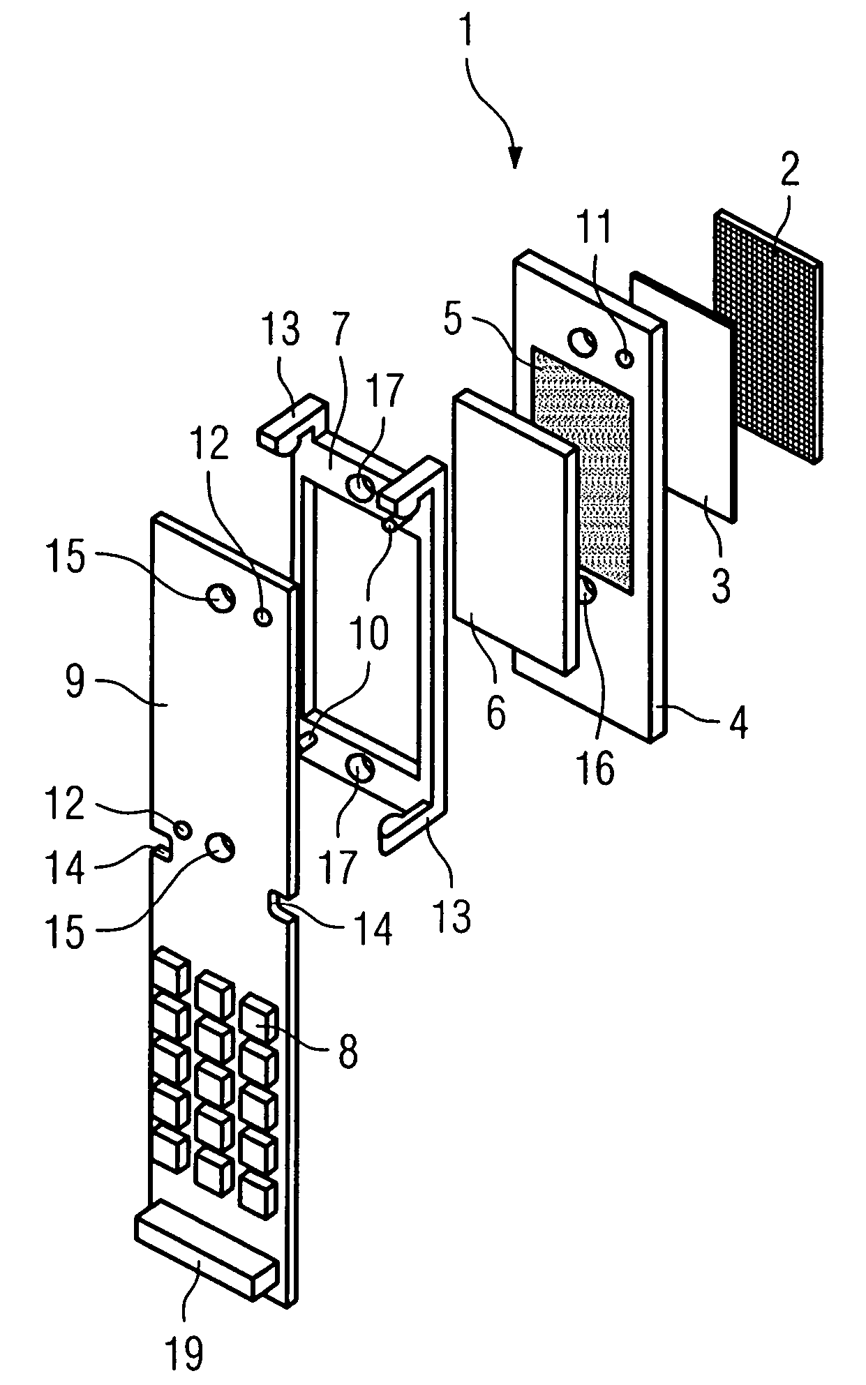
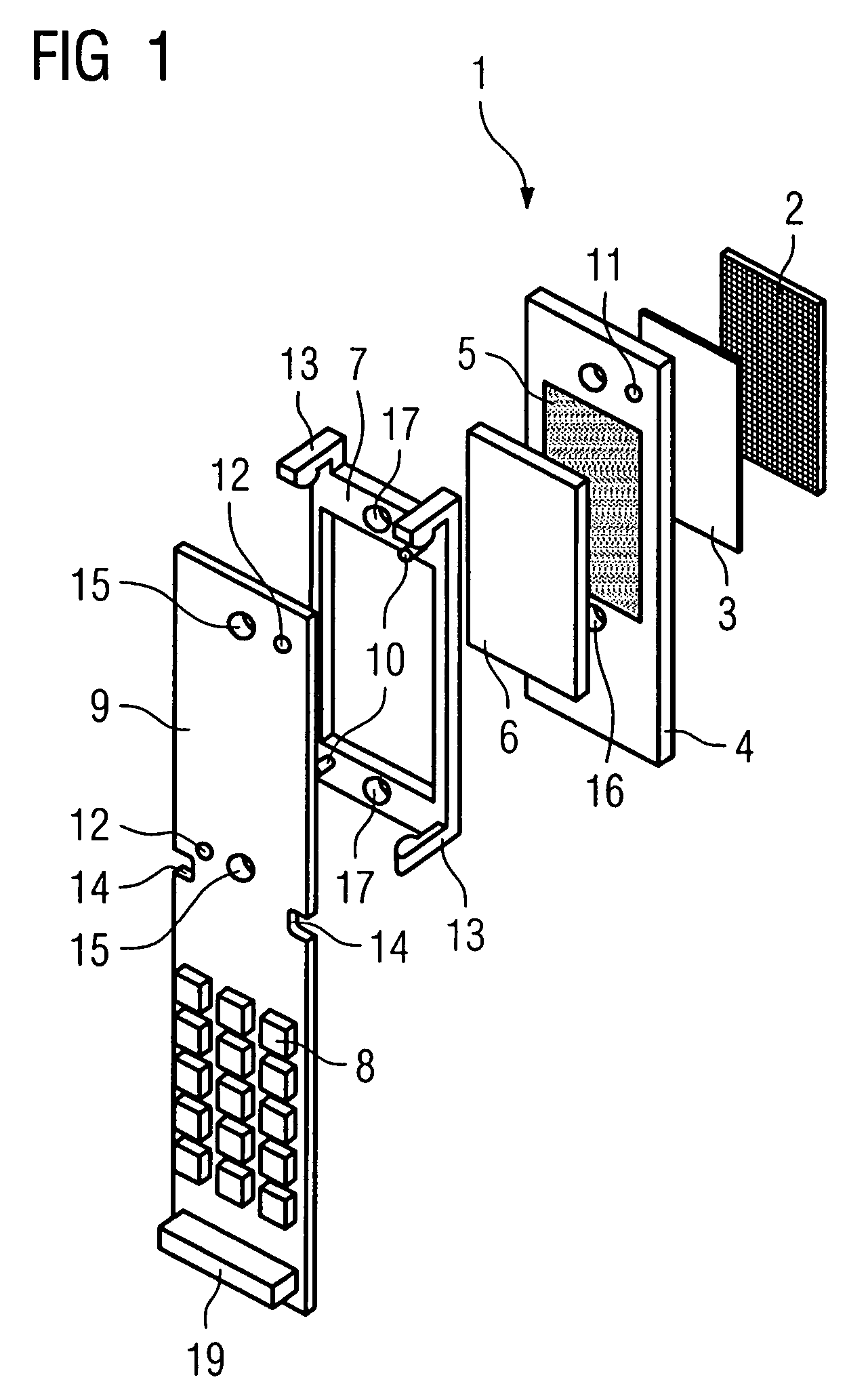
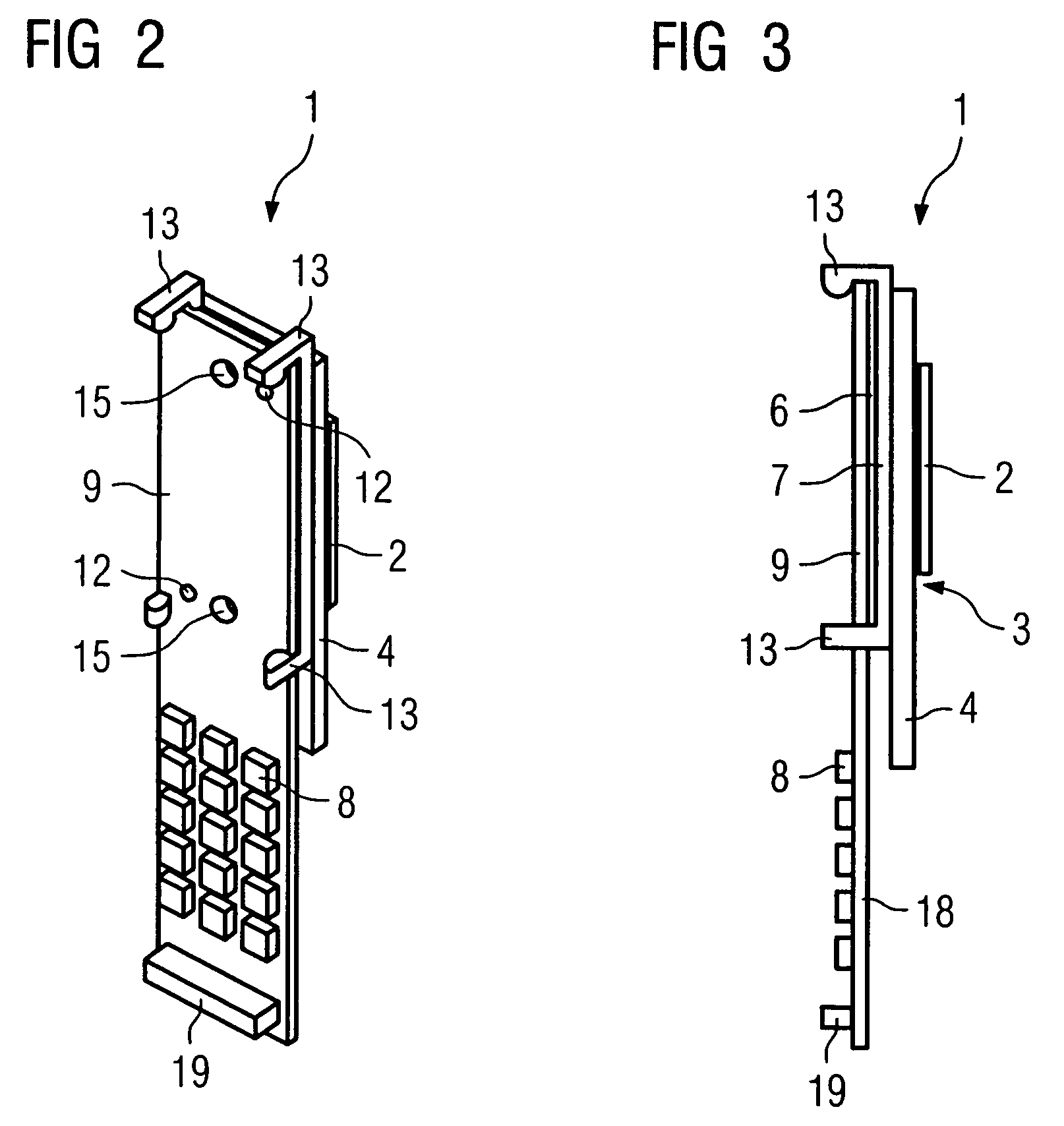
[0021]FIGS. 1 to 3 show a detector module 1. The detector module 1 has a scintillator arrangement 2 and a photodiode arrangement 3. Each scintillator of the scintillator arrangement 2 and each photodiode of the photodiode arrangement 3, which is assigned to one of the scintillators, together form a detector element. The photodiode arrangement 3 has its active side facing the scintillator arrangement 2. The scintillator arrangement 2 converts incident X-rays into light, which is converted into electrical signals by the photodiode arrangement 3.

[0022]Together with the scintillator arrangement 2 placed on it, the photodiode arrangement 3 is arranged on a module board 4. The module board 4 is provided with a multiplicity of first contact points 5. The number of first contact points 5 corresponds precisely to the number of detector elements, which are electrically connected to the first contact points 5 by way of a through-contact extending through the board.

[0023]An electrical elastomer...


PUM


Abstract

A detector module includes a plurality of detector elements, each of which is provided with a first contact point. Further, a circuit board includes second contact points. In order to be able to electrically connect a larger number of detector elements to the circuit board, the first contact points and the second contact points are arranged in a congruent grid and are electrically connected by an electrical elastomer connector.

Description

[0001]The present application hereby claims priority under 35 U.S.C. §119 on German patent application number DE 103 32 333.3 filed Jul. 16, 2003, the entire contents of which are hereby incorporated herein by reference.FIELD OF THE INVENTION[0002]The invention generally relates to a detector module. It furthermore generally relates to a detector, in particular for an X-ray computer tomograph.BACKGROUND OF THE INVENTION[0003]Such detector modules are used, for example, in detectors for X-ray computer tomographs. Incident X-rays are in this case converted into photons by a scintillator. A photodiode converts the photons into an electrical signal. The scintillator and the photodiodes are combined in a detector element. The detector element is connected to evaluation electronics, which convert the analog electrical signals into corresponding digital signals.[0004]A multiplicity of detector elements are combined in a detector module. The greater the number and the smaller the size of th...

Claims


Application Information

Patent Timeline
Patent Type & Authority Patents(United States)
IPC IPC(8): G01T1/20G01T1/24G01T1/29G01T7/00H01L23/48
CPCG01T1/2018H01L2924/0002H01L2924/00G01T1/20182
Inventor POHAN, CLAUS
Owner SIEMENS AG
Why Eureka
Try Eureka