
Method for operating a pre-crash sensing system with protruding contact sensor

a contact sensor and pre-crash sensing technology, applied in the direction of pedestrian/occupant safety arrangements, instruments, etc., can solve the problems of high hardware and algorithm complexity of pre-crash sensing systems that exist today, radar, vision and laser systems are not capable, and high reliability has not yet been achieved. , to achieve the effect of reducing false activation, reducing processing power required, and high reliability

Active Publication Date: 2007-08-21
FORD GLOBAL TECH LLC
View PDF15 Cites 65 Cited by
  • Summary
  • Abstract
  • Description
  • Claims
  • Application Information

AI Technical Summary

Benefits of technology

The present invention is an improved pre-crash sensing system that reduces false activations and identifies the stiffness of the object detected. It uses a mechanical pre-crash sensor that contains an extendable arm that can provide a high reliability verification of contact with another object prior to the object impacting the vehicle. The sensor can be added to any conventional pre-crash sensing suite, making the pre-impact deployment of non-reversible restraints feasible without a high risk of inadvertent deployments. The algorithm required to interpret the data from the mechanical pre-crash sensor is also relatively simple, reducing the processing power required and improving the software reliability of the pre-crash sensors, compared to complex, computationally demanding target identification and tracking software.

Problems solved by technology

The pre-crash sensing systems that exist today are significantly more complex than the accelerometer based systems, both in hardware and algorithm complexity.
Traditional pre-crash sensors such as radar, vision and laser systems are not capable of sensing the mass or stiffness of an object, which help define the collision severity of the crash event.
Given the complexity of the pre-crash sensing signal, along with the required fusion of targets from multiple sensors, often employing different technologies for sensing, such high reliability has not yet been achieved.
Thus, to date, all applications of pre-crash sensing to restraints have been limited to either pre-arming of non-reversible restraints (e.g. airbags), or deploying of reversible restraint devices (e.g. electromechanical seatbelt pretensioners).

Method used


Image

  • Method for operating a pre-crash sensing system with protruding contact sensor
  • Method for operating a pre-crash sensing system with protruding contact sensor
  • Method for operating a pre-crash sensing system with protruding contact sensor

Examples


Embodiment Construction

[0019]In the following figures the same reference numerals will be used to identify the same components. While the present invention is illustrated with respect to several types of pre-crash sensors, various types and combinations of pre-crash sensors may be used as will be further described below.

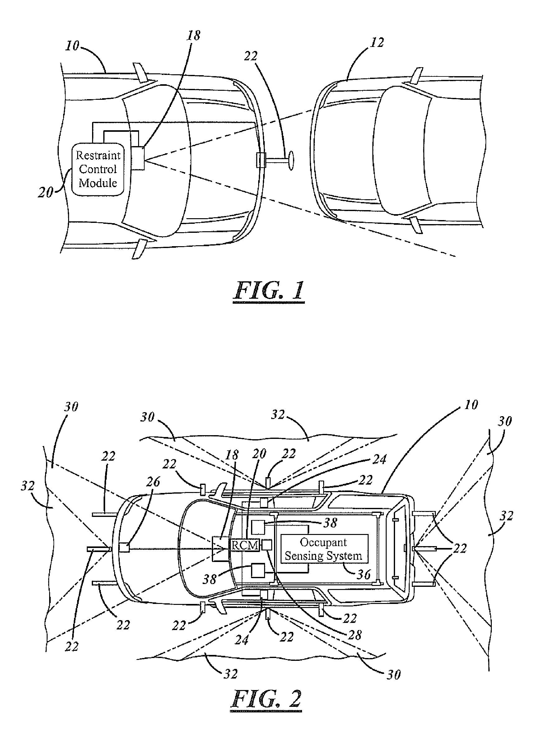
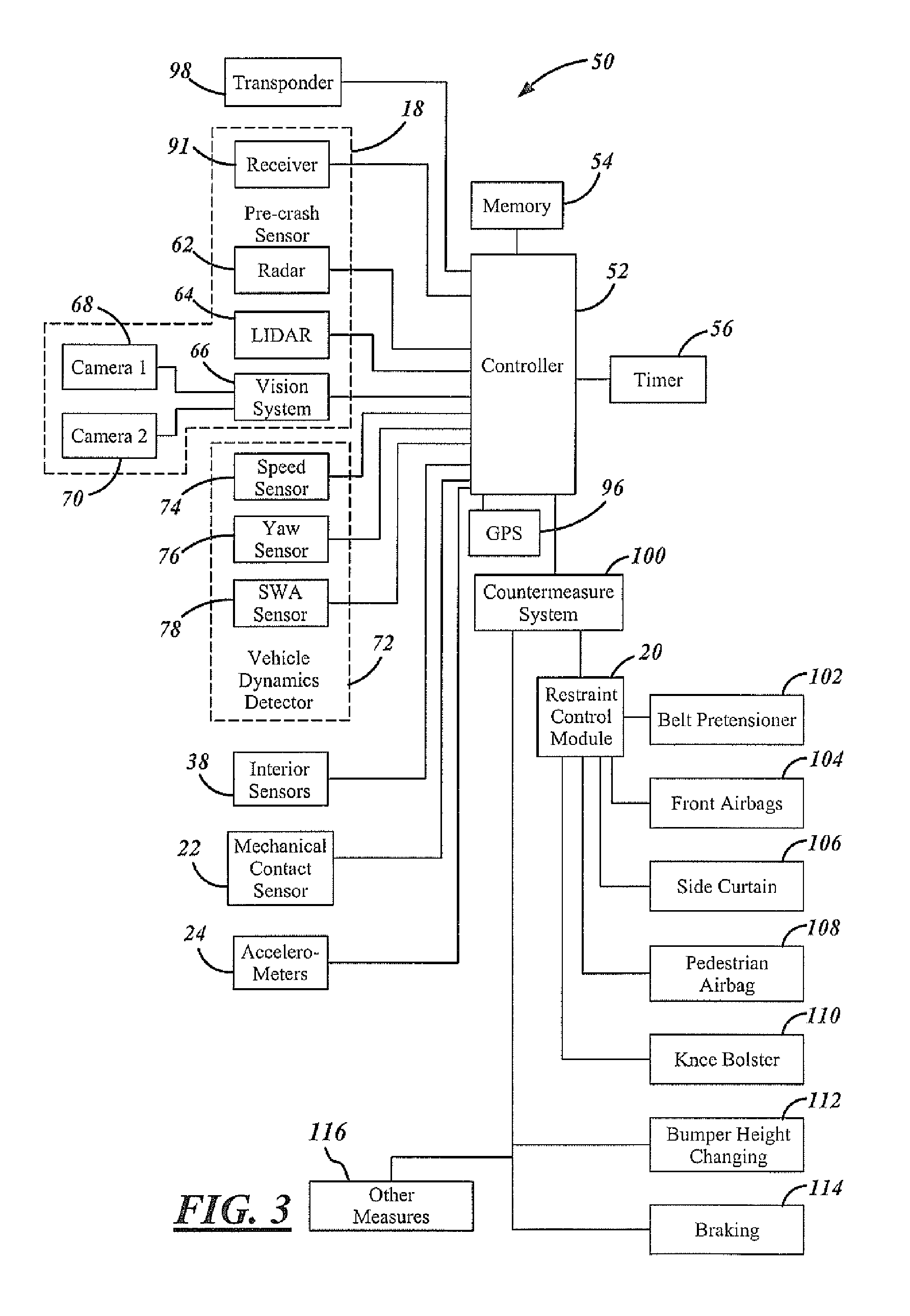
[0020]Referring now to FIG. 1, a host vehicle 10 is illustrated with respect to a crash object such as an another vehicle 12. The host vehicle 10 includes an object or pre-crash sensor 18 that is coupled to an airbag or other restraint control module (RCM) 20. In addition, a mechanical contact sensor 22 is shown protruding from the front of the vehicle. In response to the pre-crash sensor 18 and the mechanical pre-crash sensor 22, the RCM 20 activates an airbag within the vehicle as will be further described below.

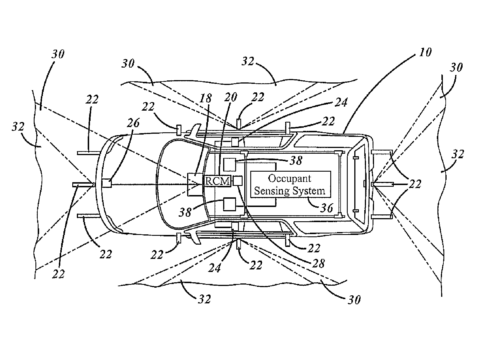
[0021]Referring now to FIG. 2, the host vehicle 10 is illustrated in further detail. The host vehicle 10 is shown having the restraint or airbag control module, RCM, 20 therein. ...


PUM


Abstract

A method of operating a restraint system includes classifying a collision into a collision classification, generating a protruding contact sensor output and deploying the restraint system in response to the contact sensor output and the output classification. The method may also use a pre-crash sensor with or without classification and deploy the restraint system in response to the pre-crash sensor signal and the protruding contact sensor signal.

Description

TECHNICAL FIELD[0001]The present invention relates to pre-crash sensing systems for automotive vehicles, and more particularly, to pre-crash sensing systems having a protruding contact sensor used for pre-crash detection.BACKGROUND[0002]Auto manufacturers are investigating radar, lidar, and vision-based pre-crash sensing systems to improve occupant safety. Pre-crash sensing systems have been recognized to have the potential of improving occupant safety by deploying the passive restraints devices earlier in a crash, or even before the actual impact. This extra time allows more flexibility for component design and can allow the passive restraints system to be individually tailored to the occupant and crash scenario.[0003]Current vehicles typically employ accelerometers that measure decelerations acting on the vehicle body in the event of a crash. In response to accelerometers, airbags or other safety devices are deployed. The pre-crash sensors also sense information before impact conc...

Claims


Application Information

Patent Timeline
Patent Type & Authority Patents(United States)
IPC IPC(8): B60R22/00G05D3/00G06F7/00G06F17/00
CPCB60R19/483B60R21/0134B60R21/0136B60R21/34B60R2021/0004B60R2021/01345B60R21/01544
Inventor RAO, MANOHARPRASAD K.CUDDIHY, MARKBAUCH, DAVIDBROWN, JOSEPH
Owner FORD GLOBAL TECH LLC
Learn More