Method for synthesizing linear finite state machines
What is Al technical title?
Al technical title is built by PatSnap Al team. It summarizes the technical point description of the patent document.
a finite state machine and linear technology, applied in the field of linear finite state machine synthesizing, can solve the problems of limited performance of the limited performance of their respective elements, and achieve the highest operating speed of conventional lfsr-based generators, encoders, decoders or compactors. performance limitation
Inactive Publication Date: 2007-08-21
SIEMENS PROD LIFECYCLE MANAGEMENT SOFTWARE INC
View PDF129 Cites 55 Cited by
Summary
Abstract
Description
Claims
Application Information
AI Technical Summary
This helps you quickly interpret patents by identifying the three key elements:
Problems solved by technology
Method used
Benefits of technology
Problems solved by technology
For high-performance applications, the required data generation and compression can only be achieved by high-performance circuits.
The highest operating speeds of conventional LFSR-based generators, encoders, decoders or compactors are limited by the performance of their respective elements.
For a type I LFSR, performance is limited by the depth (i.e., number of levels) of the combinational logic in its feedback path.
For a type II LFSR, performance is limited by buffers in the feedback path needed to compensate for internal fan-out on the output of the last stage.
In addition, the buffers slow the circuit's operation.
In both types of LFSRs, the limitations are especially pronounced for LFSRs having a characteristic polynomial with a large number of terms.
In particular, an XOR feedback network may introduce significant delays if an LFSR features a large number of feedback taps.
However, this architecture has much larger area overhead than typical LFSRs and its performance is still limited by multiplexers in the output function.
Consequently, the proposed scheme places an XOR gate and associated two-way multiplexer in the front of each LFSR stage, thus incurring significant area overhead.
None of these prior attempts, however, provides an optimal solution to the performance limitations noted above and found in presents LFSMs.
Method used
Image
Click on the blue label to locate the original text in one second.
Reading with bidirectional positioning of images and text.
Examples
Embodiment Construction
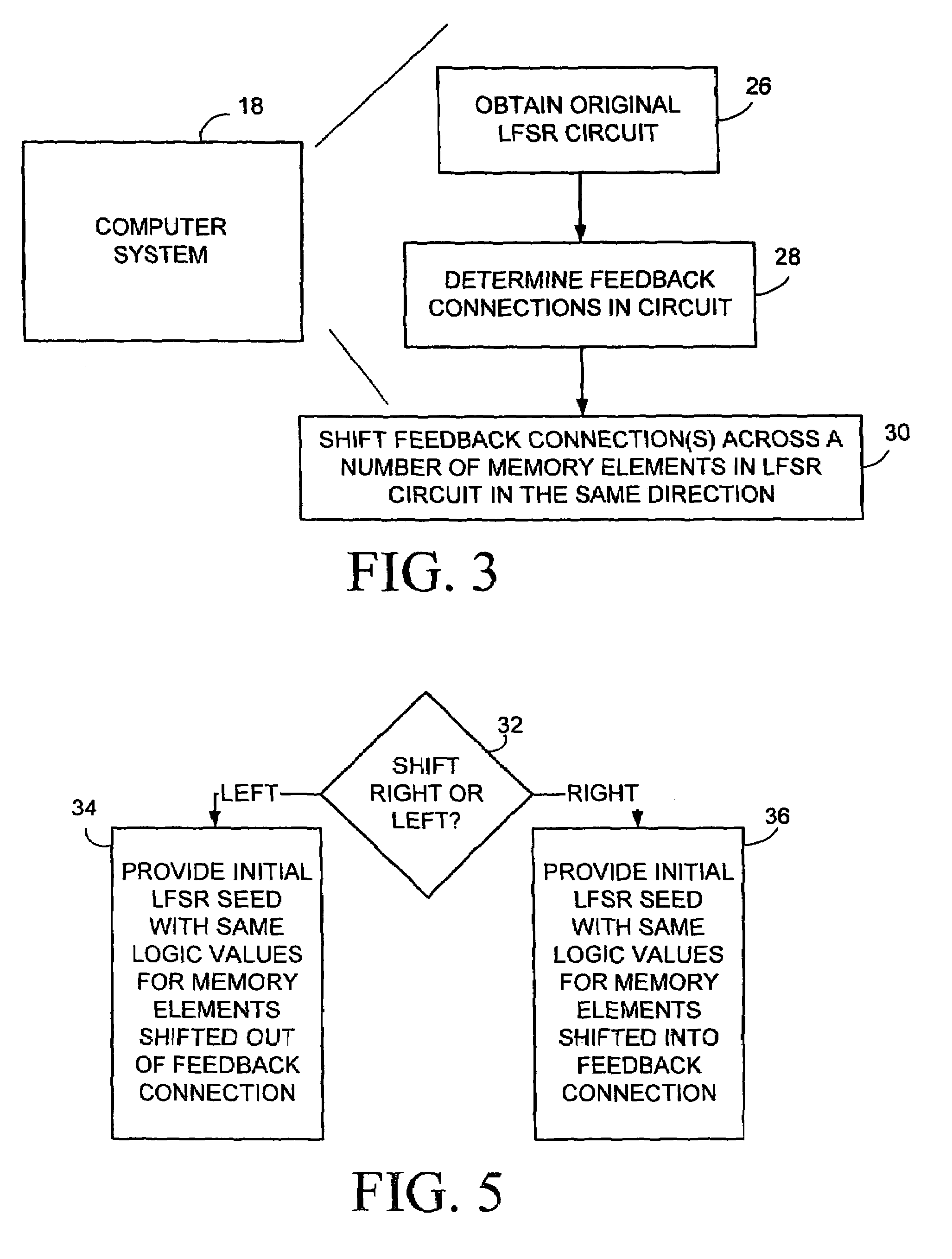
[0030]In the exemplary embodiments shown and described herein, methods for synthesizing LFSMs in accordance with the invention are implemented in software stored on a computer-readable medium and executed on a general-purpose computer system. Such a computer system is represented by block 18 in FIG. 3. The invention, for example, can be implemented in computer aided-design tools that explore the domain of possible solutions and different trade-offs concerning the layout of LFSRs. For clarity, only those aspects of the software germane to the invention are described; product details well known in the art are omitted. For the same reason, the computer hardware is not described in further detail. It should appreciated that the invention is not limited to use with computer system 18 or any particular computer language or program.
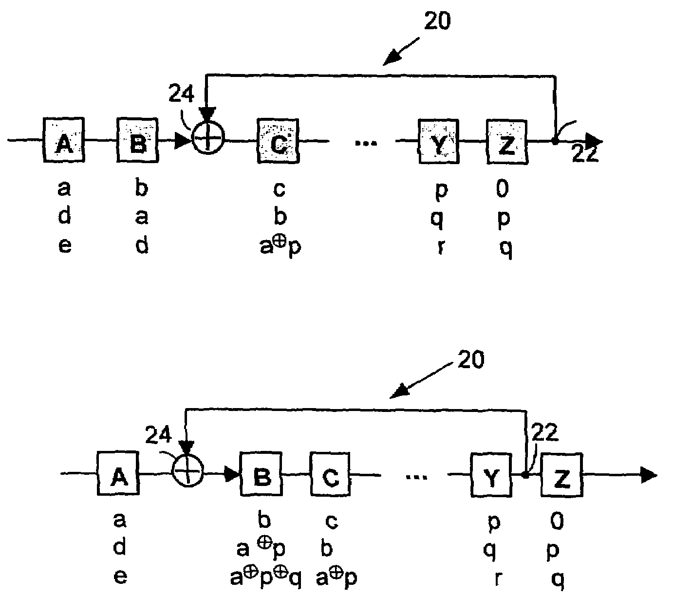
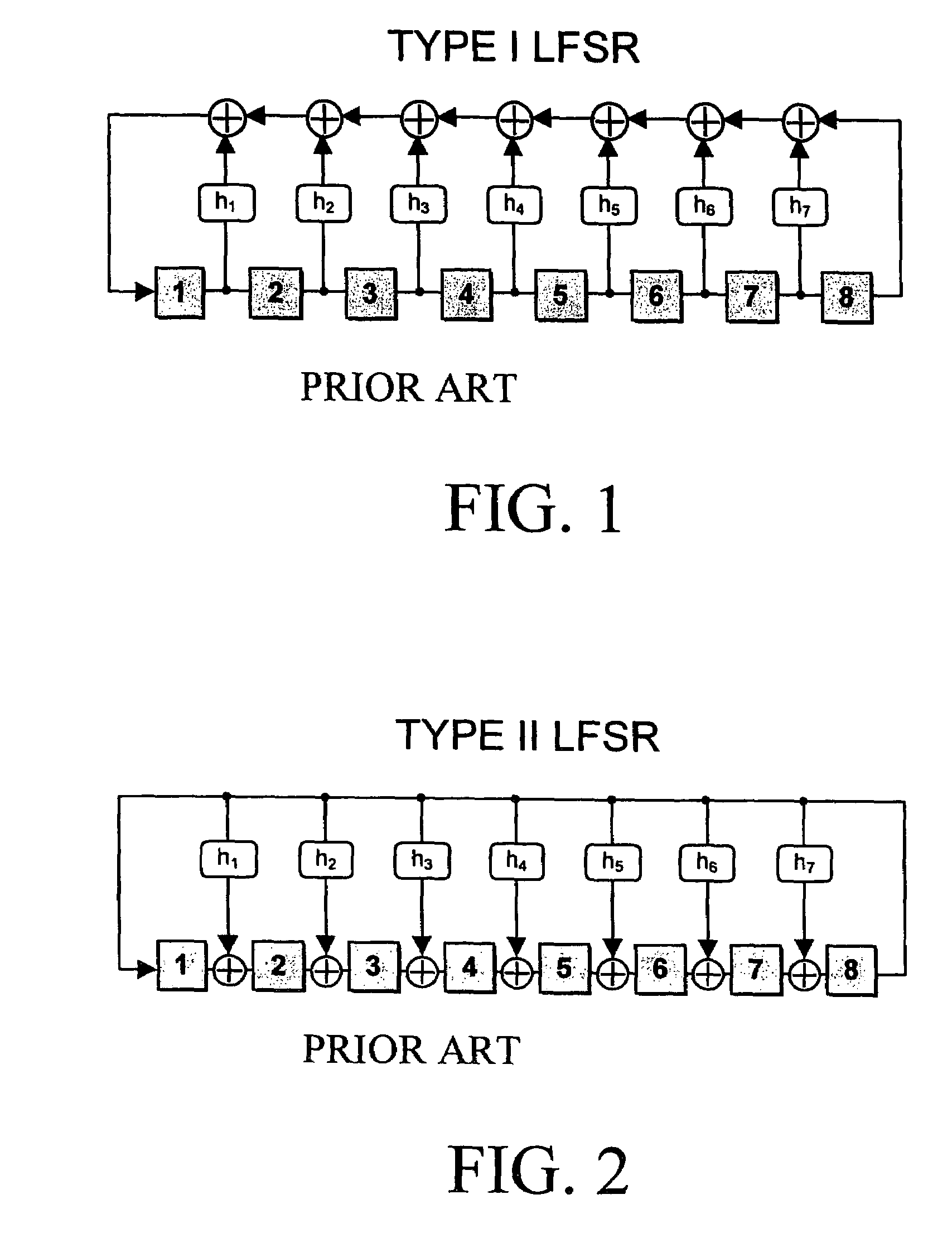
[0031]FIG. 2 shows an LFSM in the form of an arbitrary maximum-length type II LFSR with n memory elements such as flip-flops or latches and a number of feedback...
PUM
Abstract
Method and apparatus for synthesizing high-performance linear finite state machines (LFSMs) such as linear feedback shift registers (LFSRs) or cellular automata (CA). Given a characteristic polynomial for the circuit, the method obtains an original LFSM circuit such as a type I or type II LFSR. Feedback connections within the original circuit are then determined. Subsequently, a number of transformations that shift the feedback connections can be applied in such a way that properties of the original circuit are preserved in a modified LFSM circuit. In particular, if the original circuit is represented by a primitive characteristic polynomial, the method preserves the maximum-length property of the original circuit in the modified circuit and enables the modified circuit to produce the same m-sequence as the original circuit. Through the various transformations, a modified LFSM circuit can be created that provides higher performance through shorter feedback connection lines, fewer levels of logic, and lower internal fan-out.
Description
RELATED APPLICATION DATA[0001]This application is a continuation of U.S. application Ser. No. 10 / 346,699, filed Jan. 16, 2003, now U.S. Pat. No. 6,708,192 B2, which is a continuation of U.S. application Ser. No. 09 / 957,701, filed Sep. 18, 2001, now U.S. Pat. No. 6,539,409 B2, which is a continuation of U.S. application Ser. No. 09 / 620,023, filed Jul. 20, 2000, now U.S. Pat. No. 6,353,842 B1, which claims the benefit of U.S. Provisional Application No. 60 / 167,445, filed Nov. 23, 1999.BACKGROUND OF INVENTION[0002]Linear finite state machines (LFSMs) such as linear feedback shift registers (LFSRs) and cellular automata (CA) are often used for generating pseudo-random sequences. Such devices are well known in the art and are amply described in a number of references such as V. N. Yarmolik and S. N. Demidenko, Generation and Application of Pseudorandom Sequences for Random Testing, J. Wiley and Sons, New York, 1988. An LFSR includes memory elements such as flip-flops and linear logic gat...
Claims
Application Information
Patent Timeline
Application Date:The date an application was filed.
Publication Date:The date a patent or application was officially published.
First Publication Date:The earliest publication date of a patent with the same application number.
Issue Date:Publication date of the patent grant document.
PCT Entry Date:The Entry date of PCT National Phase.
Estimated Expiry Date:The statutory expiry date of a patent right according to the Patent Law, and it is the longest term of protection that the patent right can achieve without the termination of the patent right due to other reasons(Term extension factor has been taken into account ).
Invalid Date:Actual expiry date is based on effective date or publication date of legal transaction data of invalid patent.