
Reservoir tank for vehicle brake system

a technology of vehicle brake system and reserve tank, which is applied in the direction of braking system, rotary clutch, fluid coupling, etc., can solve the problems of hydraulic fluid blown, limited mounting position, and /b> may find its way into the eye of the operator, and achieve the effect of preventing stains and preventing stains

Active Publication Date: 2007-08-28
ADVICS CO LTD
View PDF7 Cites 13 Cited by
  • Summary
  • Abstract
  • Description
  • Claims
  • Application Information

AI Technical Summary

Benefits of technology

[0011]With this arrangement, simply by fitting the plate member on the tubular portion, the deflector plate can be positioned properly.
[0013]With this arrangement, since the deflector plate and the filter are preassembled, they can be made smaller in size and manufactured at a lower than when they are prepared separately from each other. Preferably, the plate member is a bottom wall of a box-shaped member supported by the partitioning wall because such a box-shaped member can be more easily supported by the partitioning wall.
[0016]The deflector prevents hydraulic fluid discharged into the reservoir tank through the inlet / outlet port from being blown out through the hydraulic fluid supply port even if the hydraulic fluid supply port is open. This prevents deterioration in the work environment and health hazard.

Problems solved by technology

Because this type of reservoir tank is installed in a narrow, limited space in a vehicle engine room, its mounting position is limited.
Hydraulic fluid blown out through the port 113 may find its way into an operator's eye or stain clothes.
This causes deterioration in the work environment and health hazard.

Method used


Image

  • Reservoir tank for vehicle brake system
  • Reservoir tank for vehicle brake system
  • Reservoir tank for vehicle brake system

Examples


Embodiment Construction

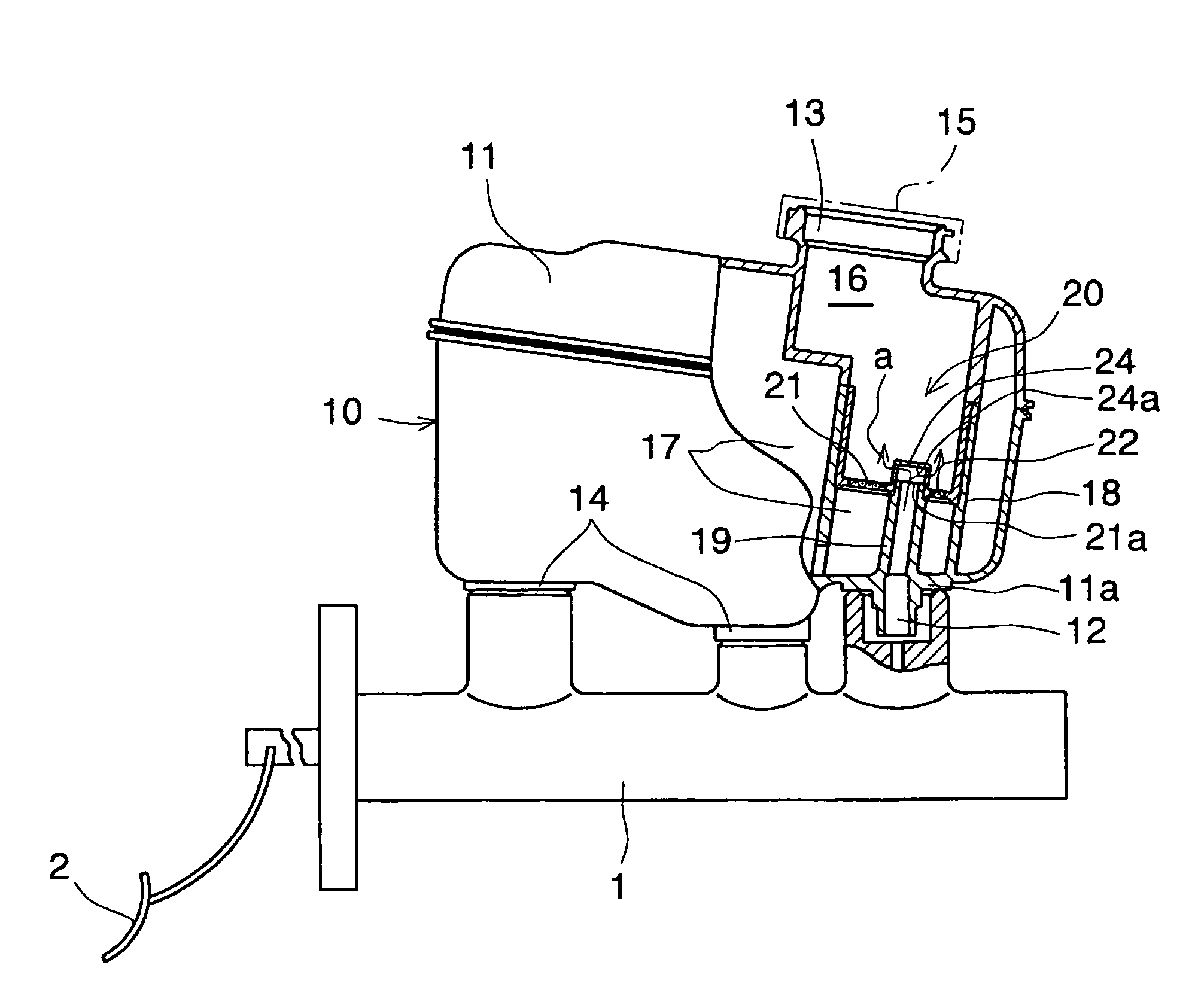
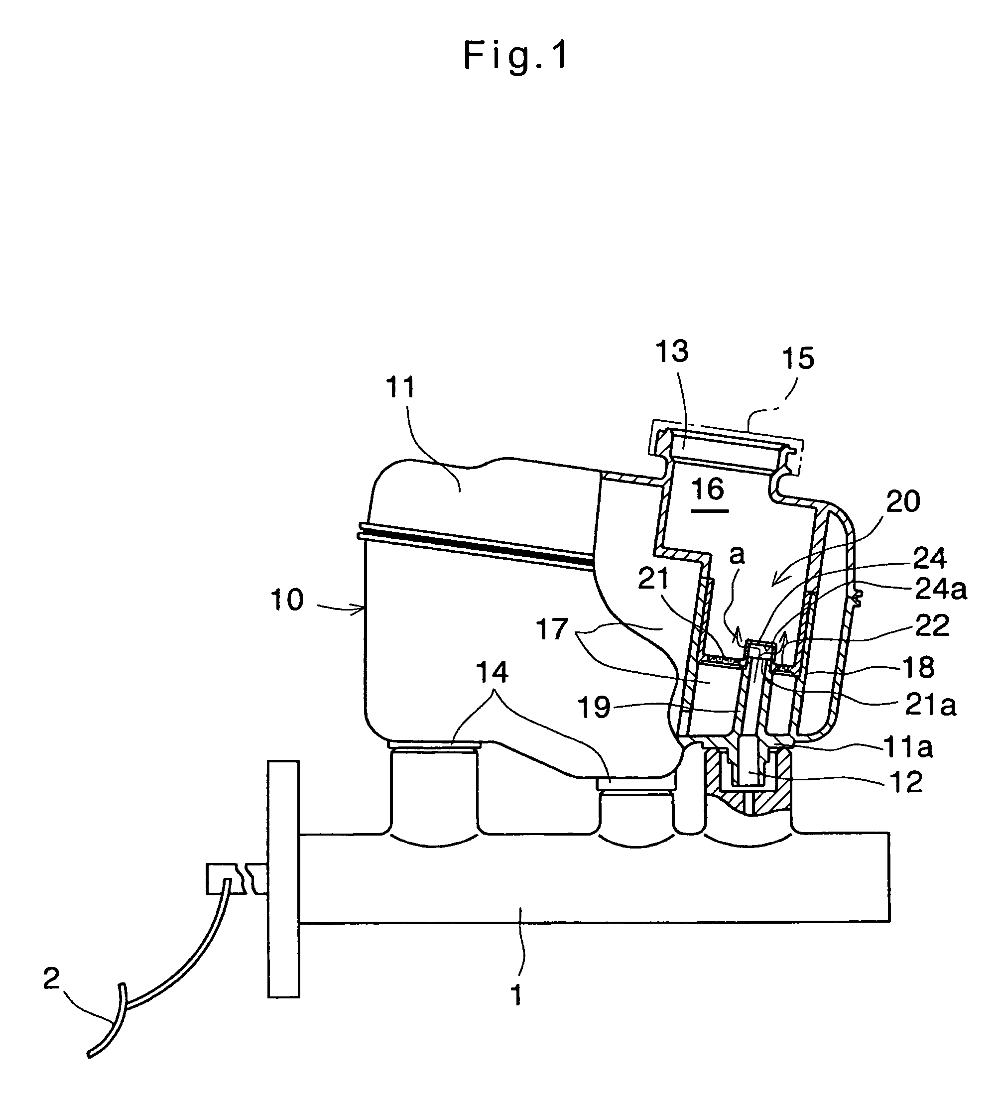
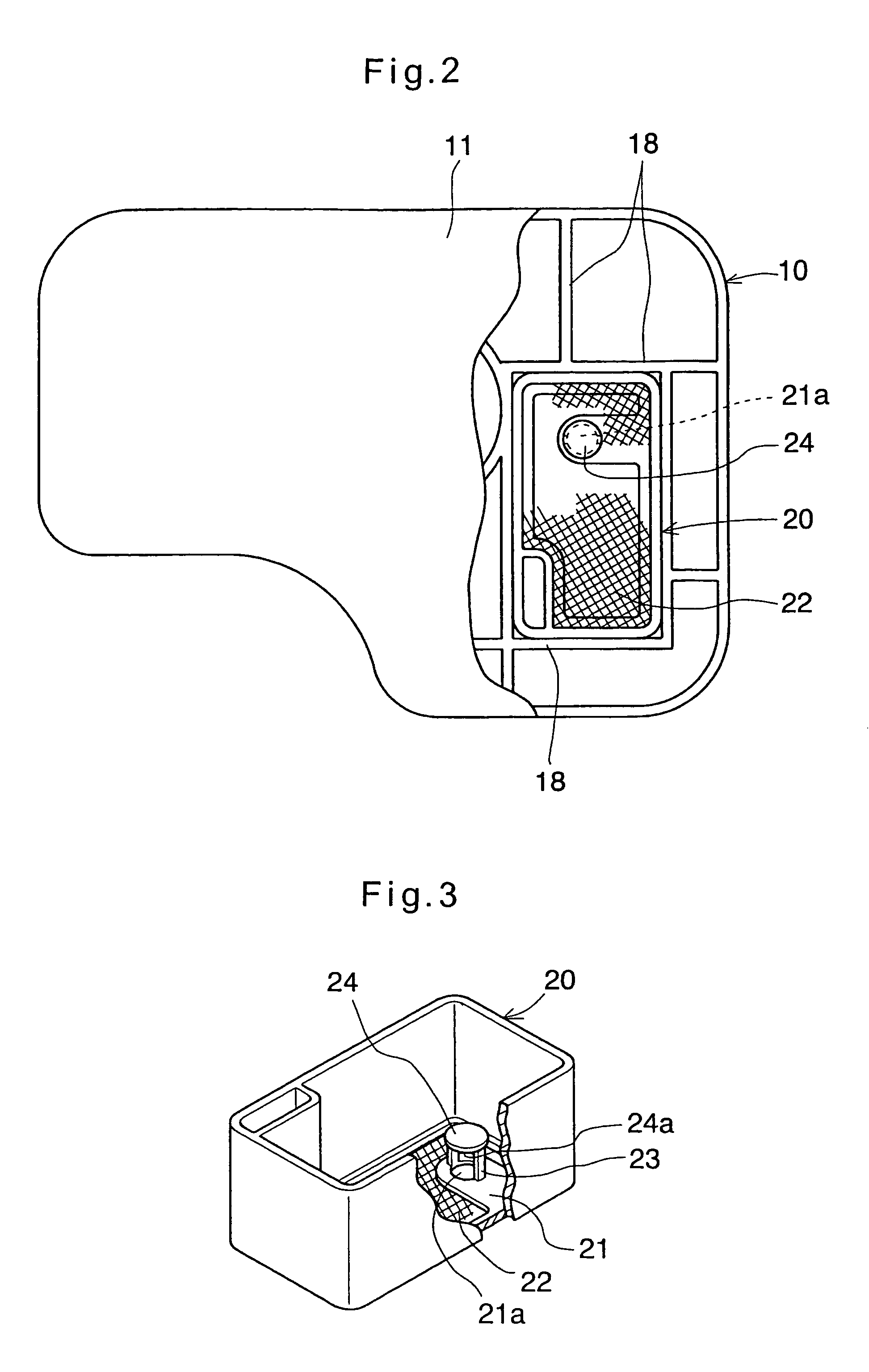
[0026]The embodiment of FIGS. 1-3 is a reservoir tank 10 in a vehicle brake system for controlling brake hydraulic pressure. The reservoir tank 10 includes a tank body 11 formed of a synthetic resin and mounted on a master cylinder 1 with its ports 12 and 14 connected to corresponding ports of the master cylinder 1. A partitioning wall 18 is provided in the tank body 11. (Throughout the drawings, not the entire partitioning wall 18 is shown.) The partitioning wall 18 prevents pulsation of hydraulic fluid a. As shown in FIGS. 1 and 2, an open-topped box-shaped member 20 (see FIG. 3) is supported by the partitioning wall 18. The box member 20 has a bottom plate 21. The partitioning wall 18 and the bottom plate 21 of the box member 20 divide the interior of the tank 10 into a first fluid chamber 16 and a second fluid chamber 17. The tank 10 is formed with a hydraulic fluid supply port 13 communicating with the first fluid chamber 16. The outlet ports 14, through which hydraulic fluid a...


PUM


Abstract

A reservoir tank has an inlet / outlet port communicating with a master cylinder, and a hydraulic fluid supply port provided directly opposite the inlet / outlet port. A tubular portion is provided on the inner surface of the tank. The tubular portion has an internal passage communicating with the inlet / outlet port and having a top opening. A box-shaped member has its bottom plate fitted on the tubular member. The bottom plate is formed of a filter material. A deflector plate is supported on legs extending upwardly form the bottom plate of the box member so as to be disposed right over the top opening of the tubular portion. The deflector plate deflects the flow of hydraulic fluid such that it will not be directed toward the hydraulic fluid supply port, thereby preventing hydraulic fluid from being blown out through the hydraulic fluid supply port even if this port is open.

Description

BACKGROUND OF THE INVENTION[0001]This invention relates to a reservoir tank which is structured to be mounted on a master cylinder or a hydraulic pressure booster in a vehicle brake system.[0002]FIG. 10 shows a conventional reservoir tank of this type which is disclosed in unexamined JP patent publication 10-35469. This reservoir tank, generally designated 110, comprises a tank body 111 made of a synthetic resin, and mounted on a master cylinder 1 with its ports 112 and 114 connected to corresponding ports of the master cylinder 1. The body 111 has a hydraulic fluid supply port 113 in its top through which hydraulic fluid a is supplied into the tank 110. Through the ports 112, hydraulic fluid flows between the reservoir and the master cylinder. Through the ports 114, hydraulic fluid a is supplied to the master cylinder 1 and / or hydraulic units such as pumps. Numeral 115a designates a strainer.[0003]JP patent publication 06-156254 discloses a similar reservoir tank of which the inter...

Claims


Application Information

Patent Timeline
Patent Type & Authority Patents(United States)
IPC IPC(8): B60T17/00B60T11/26B60T11/22B60T17/06
CPCB60T11/22B60T17/06
Inventor HAYASHI, MITSUHARU
Owner ADVICS CO LTD
Learn More