Printing device with radiation source

a printing device and radiation source technology, applied in printing, other printing apparatus, etc., can solve the problems of increased heat, ineffective use of additional power, environmental protection and cost, and inability to effectively irradiate etc., to achieve the effect of irradiating the deposited marking substance more effectively

Active Publication Date: 2007-08-28
OCE DISPLAY GRAPHICS SYST
View PDF2 Cites 8 Cited by
  • Summary
  • Abstract
  • Description
  • Claims
  • Application Information

AI Technical Summary

Benefits of technology

[0007]It is an object of the present invention to provide a radiation source moveable in co-operation with the moveable carriage of a printing device which irradiates the deposited marking substance more effectively, particularly when the printing device is operated in a multiple printing stage mode.
[0008]It is a further object of the present invention to provide a radiation source moveable in co-operation with the moveable carriage of a printing device which ensures that all dots of marking substance deposited on an image-receiving member receive at least a predetermined minimum radiation dose, regardless of whether the printing device is operated in a single or multiple printing stage mode, without substantially increasing the overall output power level of the radiation source.

Problems solved by technology

Both “interlace systems” and “multi-pass systems” as well as combinations thereof share the advantage of an improved image quality but also the inherent disadvantage of a lower productivity.
Besides the fact that such ineffective use of additional power is environmentally unfriendly and costly, there may be some additional disadvantages associated with the use of an increased output power level.
For instance, the increase in power level also results in an increase of heat which is particularly undesired when curing ink deposited on thermal sensitive image-receiving members.
Moreover, part of the ink deposited is exposed to multiple traverses of the UV lamp, which output level is increased, and hence overcuring may occur as some inks are sensitive thereto.

Method used


Image

  • Printing device with radiation source
  • Printing device with radiation source
  • Printing device with radiation source

Examples


Embodiment Construction

[0021]In relation to the appended drawings, the present invention is described in detail. Several embodiments are disclosed. Although in the embodiments disclosed, the marking substance is a UV curable ink and the radiation sources are xenon flash lamps, it is apparent that a person skilled in the art can imagine several other equivalent embodiments or other ways of executing the present invention. In particular, the marking substance may be any marking substance which can be discharged in fluid form including but not limited to a solvent or aqueous based ink, an UV curable ink, a liquid toner, and a hot melt ink. The radiation source may be a drying source including a halogen lamp or a curing source including mercury vapour lamps, xenon flash lamps, and LED's.

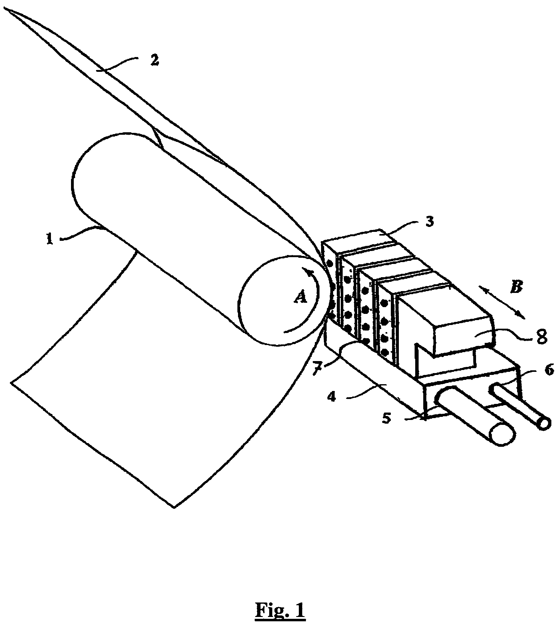
[0022]The printing device of FIG. 1 is an inkjet printer suited for printing with UV curable ink. The printing device comprises a roller (1) for supporting an image-receiving member (2) which is moved along four print heads (3...


PUM


Abstract

A printing device and method containing a carriage supporting print heads with a plurality of discharging elements to the image-wise forming of image dots of a marking substance on an a print medium, wherein the carriage is moveable in reciprocation in a main scanning direction and is also relatively displaceable with respect to the print medium in the sub scanning direction. Moreover, at least one radiation source is provided for irradiating the image dots of marking substance. The radiation source is designed such that the print medium with the dots formed thereon receives, in a traverse of the radiation source, a radiation dose which increases towards an edge of the dimension in the sub scanning direction of the area irradiated by the radiation source in the traverse.

Description

FIELD OF THE INVENTION[0001]The present invention relates to a printing device such as a printing or copying system employing print heads containing discharging elements, e.g. nozzles, for image-wise forming dots of a marking substance on an image-receiving member, where the marking substance is in fluid form when discharged and is thereafter exposed to a radiation source. In particular, the marking substance may be a UV curable ink, while the radiation source is a UV radiation curing source.BACKGROUND OF THE INVENTION[0002]Print heads employed in inkjet printers and the like usually contain a plurality of nozzles arranged in (an) array(s). The nozzles usually are placed substantially equidistant. The distance between two contiguous nozzles defines the nozzle pitch. In operation, the nozzles are controlled to the image-wise discharge of fluid droplets of a marking substance on an image-receiving member. When the printer is of the scanning type, the print heads are supported on a car...

Claims


Application Information

Patent Timeline
Patent Type & Authority Patents(United States)
IPC IPC(8): B41J2/01
CPCB41J11/002B41J11/0021B41J11/00214
Inventor OTTER, BRIAN D.
Owner OCE DISPLAY GRAPHICS SYST
Why Eureka
Try Eureka