Assembly for maintaining compression for electrical contact of the active area of an electrochemical cell

a cell and active area technology, applied in the field of cell structure of an electrochemical cell, can solve the problems of difficult analysis and manufacture of current pressure pads, difficult to achieve accurate and consistent spring rates, and the need for springs to provide only sufficient preload

Active Publication Date: 2007-08-28
HAMILTON SUNDSTRAND CORP
View PDF10 Cites 2 Cited by
  • Summary
  • Abstract
  • Description
  • Claims
  • Application Information

AI Technical Summary

Benefits of technology

[0008]The present invention eliminates the need for a pressure pad entirely. Rather than use a pressure pad, the invention uses a spring as a resilient member to force the active areas of the anode cavity and the cathode cavity together. The spring is compatible with the fluids exchanged between the anode cavity and the cathode cavity. Consequently, the separator plate between the cavities and the pressure pad may be eliminated. By eliminating the separator plate, the spring need not be preloaded to accommodate for the pressure differential between the anode cavity and the cathode cavity. The spring will be at pressure equilibrium with pressure within the cavities since it does not block flow of fluid. Therefore, the spring need only provide sufficient preload to bias the anode cavity and the cathode cavity together. This preload is significantly smaller than the preload required for device using a pressure pad.

Problems solved by technology

Therefore, the spring need only provide sufficient preload to bias the anode cavity and the cathode cavity together.
Current pressure pads are difficult to analyze and manufacture.
Accordingly, accurate and consistent spring rates are difficult to achieve.

Method used


Image

  • Assembly for maintaining compression for electrical contact of the active area of an electrochemical cell
  • Assembly for maintaining compression for electrical contact of the active area of an electrochemical cell
  • Assembly for maintaining compression for electrical contact of the active area of an electrochemical cell

Examples


Embodiment Construction

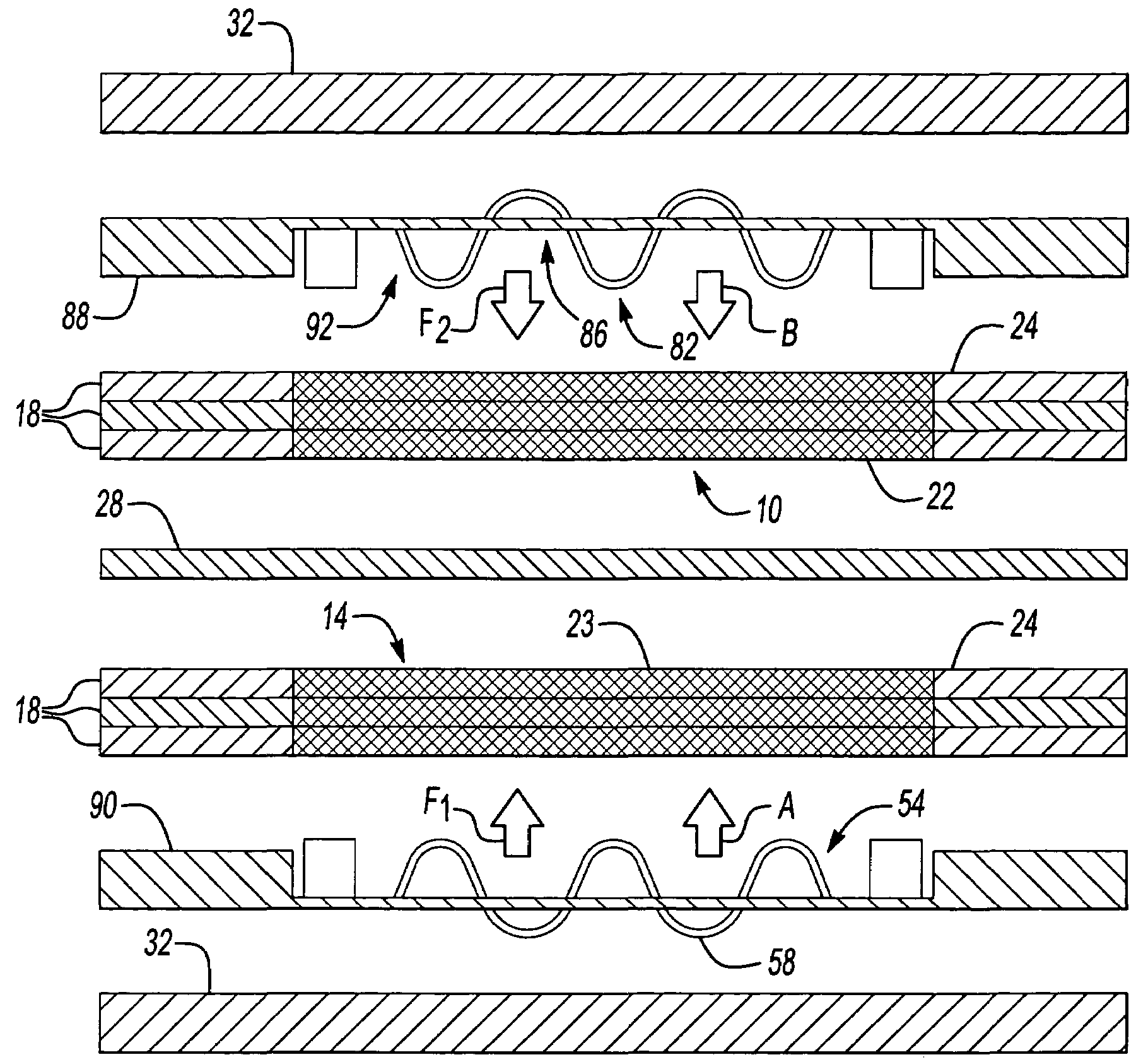
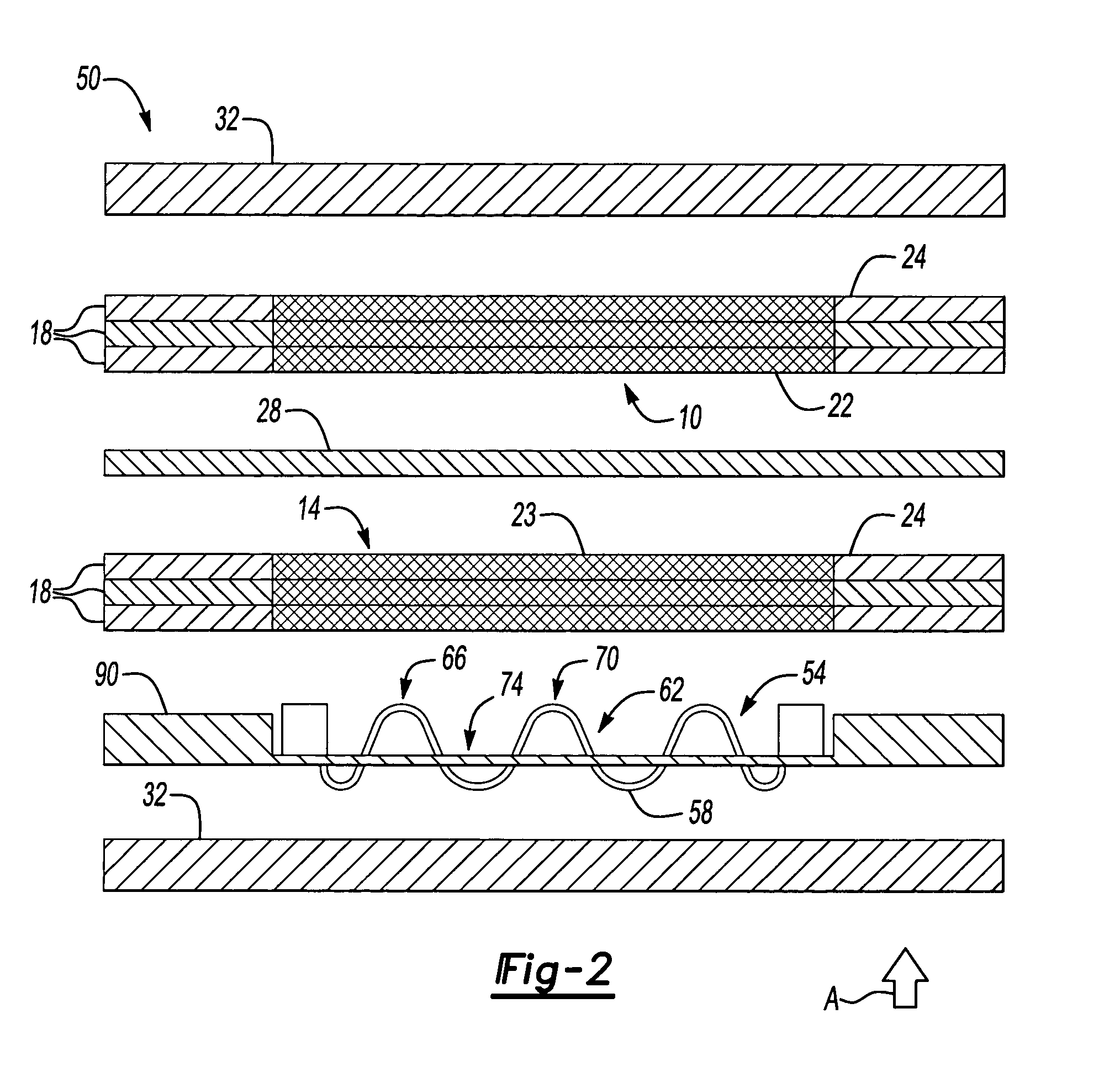
[0020]FIG. 2 illustrates an exploded view of inventive electrochemical cell structure 50, here an electrochemical cell. Electrochemical cell structure 50 may comprise anode cavity 10 and cathode cavity 14 sandwiched between separator plates 32. Like the prior art, anode cavity 10 and cathode cavity 14 comprise plates having mesh screens with openings forming an active area 22 for anode cavity 10 and an active area 23 for cathode cavity 14. Inactive area 24 of anode cavity 10 and cathode cavity 14 form a fluid barrier to contain fluid within active area 22 and active area 23. Anode cavity 10 and cathode cavity 14 sandwich electrochemically conductive medium 28, such as an ion-exchange membrane or liquid contained in a porous matrix. In contrast to known assemblies, electrochemical cell structure 50 has a spring, resilient member 58 to bias cathode cavity 14 towards anode cavity 10 in the direction of arrow A. In the example shown, resilient member 58 is a wave spring characterized by...


PUM

PropertyMeasurementUnit
electrically conductiveaaaaaaaaaa
spring forceaaaaaaaaaa
ionically conductiveaaaaaaaaaa

Abstract

An electrochemical cell structure has a first fluid chamber and a resilient member disposed in the first fluid chamber. An opening permits communication of fluid into the first fluid chamber. An anode cavity and a cathode cavity are in fluid communication with the fluid chamber through the opening.

Description

BACKGROUND OF THE INVENTION[0001]This invention relates to a cell structure for an electrochemical cell.[0002]An electrochemical cell may be used to electrolytically separate water into its components, hydrogen and oxygen or, alternatively, combine hydrogen with oxygen to generate electricity. Each electrochemical cell typically has an anode cavity, a cathode cavity and an electrolyte. The electrolyte may be an ionically conductive material, such as an ion-exchange membrane or liquid contained in a porous matrix. The electrolyte is positioned between the anode cavity and the cathode cavity and serves to control the exchange of electrical charge and fluid between the two cavities.[0003]FIG. 1 illustrates an exploded view of an electrochemical cell 12 known in the art. As shown, electrochemical cell 12 has anode cavity 10 and cathode cavity 14 arranged between separator plates 32. Each cavity 10, 14 comprises a series of electrically conductive round metal plates 18, which are stacked...

Claims


Application Information

Patent Timeline
Patent Type & Authority Patents(United States)
IPC IPC(8): C25B9/00H01M2/08H01M4/00H01M8/02H01M8/24
CPCH01M8/0247H01M8/247H01M8/0206Y02E60/50H01M8/02H01M8/24
Inventor MANN, JOHN CALVIN
Owner HAMILTON SUNDSTRAND CORP
Why Eureka
Try Eureka